NOTE: When writing mac- ros to control VCR opera- tion, keep in mind the follow- ing:
The macro must reflect your actual equipment configura- tion; if you change the con- figuration, you must adjust the macro accordingly. For example, if a macro were written to control VCRs at- tached to three
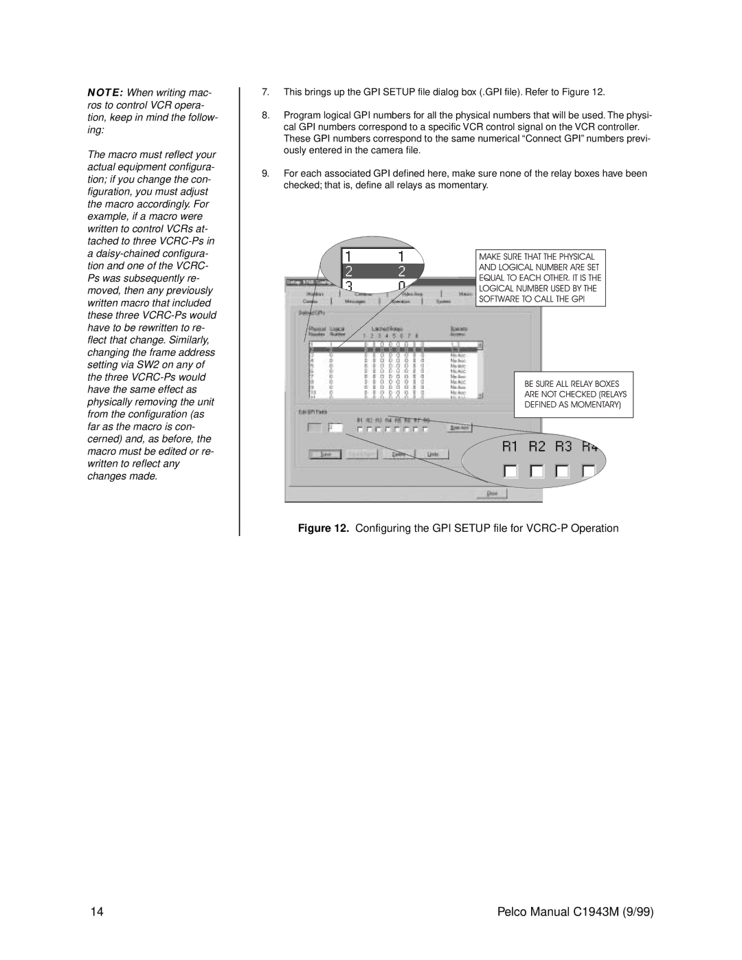
7.This brings up the GPI SETUP file dialog box (.GPI file). Refer to Figure 12.
8.Program logical GPI numbers for all the physical numbers that will be used. The physi- cal GPI numbers correspond to a specific VCR control signal on the VCR controller. These GPI numbers correspond to the same numerical “Connect GPI” numbers previ- ously entered in the camera file.
9.For each associated GPI defined here, make sure none of the relay boxes have been checked; that is, define all relays as momentary.
Figure 12. Configuring the GPI SETUP file for VCRC-P Operation
14 | Pelco Manual C1943M (9/99) |