RELAY OUTPUT CONNECTOR
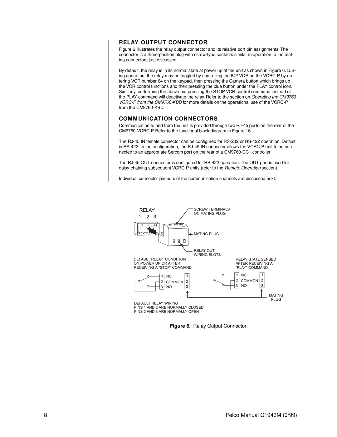
Figure 6 illustrates the relay output connector and its relative port pin assignments. The connector is a three-position plug with screw-type contacts similar in operation to the mat- ing connectors just discussed.
By default, the relay is in its normal state at power up of the unit as shown in Figure 6. Dur- ing operation, the relay may be toggled by controlling the 64th VCR on the VCRC-P by en- tering VCR number 64 on the keypad, then pressing the Camera button which brings up the VCR control functions and then pressing the blue button under the PLAY control icon. Similarly, performing the above but pressing the STOP VCR control command instead of the PLAY command will deactivate the relay. Refer to the section on Operating the CM9760- VCRC-P from the CM9760-KBD for more details on the operational use of the VCRC-P from the CM9760-KBD.
COMMUNICATION CONNECTORS
Communication to and from the unit is provided through two
The
The
Individual connector
Figure 6. Relay Output Connector
8 | Pelco Manual C1943M (9/99) |