OPERATIONAL OVERVIEW
The basic function of the
When power is first applied to the unit, RAM is cleared and initialization routines are called. The power LED is lit, operational chips are configured, interrupt priorities are set and the activity LED on the front panel of the unit flashes on and off at about 1/2 second intervals. The unit is waiting for its first valid command.
FUNCTIONAL BLOCK DIAGRAM
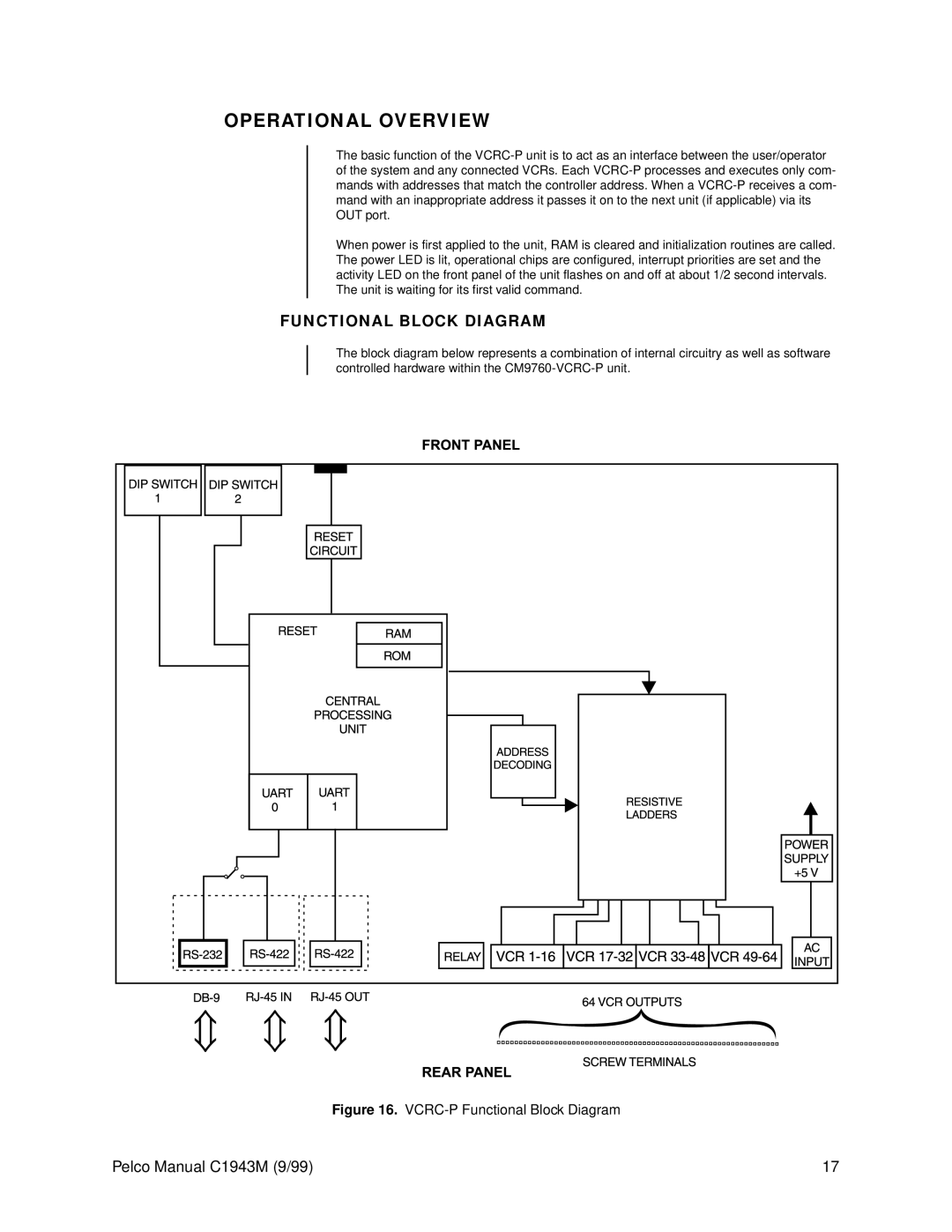
The block diagram below represents a combination of internal circuitry as well as software controlled hardware within the
Figure 16. VCRC-P Functional Block Diagram
Pelco Manual C1943M (9/99) | 17 |