IMPORTANT:
Control cable length should not
be extended further than the supplied 50 feet (15.2 m). It is also recommended that shielded cable be used to minimize external electrical interference with VCRC-P control signals.You should also avoid ground loops of any kind. See important note in Figure 9 regarding power hookup and interference.
INPUT VCR CONNECTORS
Physically, each of the four VCRC-P input connectors consists of the same number of input screw-type terminals. Each input group uses a dual-row removable plug and each plug is associated with 8 VCR inputs.
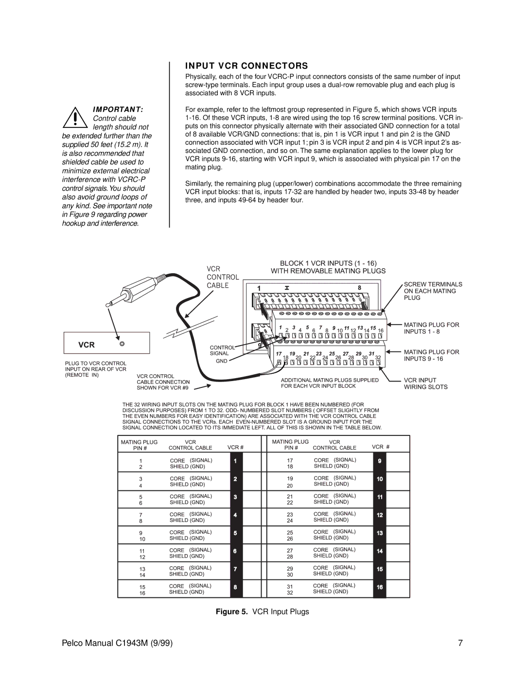
For example, refer to the leftmost group represented in Figure 5, which shows VCR inputs
1-16. Of these VCR inputs, 1-8 are wired using the top 16 screw terminal positions. VCR in- puts on this connector physically alternate with their associated GND connection for a total of 8 available VCR/GND connections: that is, pin 1 is VCR input 1 and pin 2 is the GND connection associated with VCR input 1; pin 3 is VCR input 2 and pin 4 is VCR input 2’s as- sociated GND connection, and so on. The same explanation applies to the lower plug for VCR inputs 9-16, starting with VCR input 9, which is associated with physical pin 17 on the mating plug.
Similarly, the remaining plug (upper/lower) combinations accommodate the three remaining VCR input blocks: that is, inputs 17-32 are handled by header two, inputs 33-48 by header three, and inputs 49-64 by header four.