MODELS
| VCR control unit capable of controlling 64 VCRs per unit. VCR | |
|
| control is specific to Pelco TLR2096. |
OPTIONS |
| |
|
| A |
| ||
|
| end (for connecting to VCR) and cord/shield (signal/ground) bare |
|
| wires at the opposite end for connection to input mating plugs lo- |
|
| cated on rear of |
|
|
|
PRE-INSTALLATION INFORMATION
FRONT VIEW
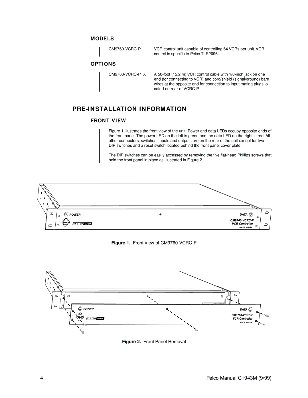
Figure 1 illustrates the front view of the unit. Power and data LEDs occupy opposite ends of the front panel. The power LED on the left is green and the data LED on the right is red. All other connectors, switches, inputs and outputs are on the rear of the unit except for two DIP switches and a reset switch located behind the front panel cover plate.
The DIP switches can be easily accessed by removing the five flat-head Phillips screws that hold the front panel in place as illustrated in Figure 2.
Figure 1. Front View of CM9760-VCRC-P
Figure 2. Front Panel Removal
4 | Pelco Manual C1943M (9/99) |
