HOOKING UP ACCESSORY DEVICES
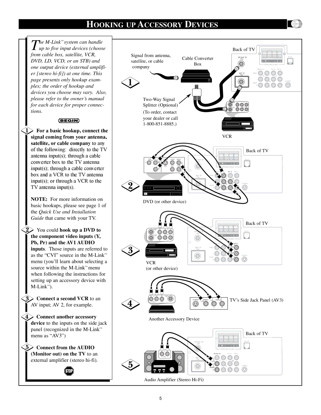
The M-Link™ system can handle up to five input devices (choose
from cable box, satellite, VCR, DVD, LD, VCD, or an STB) and one output device (external amplifi- er [stereo
![]() For a basic hookup, connect the signal coming from your antenna, satellite, or cable company to any of the following: directly to the TV antenna input(s); through a cable converter box to the TV antenna input(s); through a cable converter box and a VCR to the TV antenna
For a basic hookup, connect the signal coming from your antenna, satellite, or cable company to any of the following: directly to the TV antenna input(s); through a cable converter box to the TV antenna input(s); through a cable converter box and a VCR to the TV antenna
|
| Back of TV |
Signal from antenna, |
| 8 |
Cable Converter | PIP ANT "B" | |
satellite, or cable | 75Ω | |
Box | + R – – L + | |
company | SURROUND SOUND | |
|
|
(To order, contact your dealer or call
COMP VIDEO | VIDEO | AUDIO | |
Y | Pb |
| R |
| OUT | OUT | OUT |
| Pr |
| L |
| Monitor out | AV1 in AV2 in |
ANT "A" | VIDEO |
|
75Ω |
| Y |
|
| |
| L |
|
| AUDIO | Pb |
|
| |
| R |
|
|
| Pr |
ANTENNA | OUT | OUT |
OUT | ||
ANTENNA | VIDEO | R AUDIO L |
IN |
|
|
| IN | IN |
VCR
Back of TV
8 | 8 |
PIP ANT "B" |
|
| |
75Ω |
|
|
|
+ | R – | – L | + |
| SURROUND SOUND |
| |
Monitor out | AV1 in AV2 in |
ANT "A" | VIDEO |
75Ω | Y |
|
8![]()
input(s); or through a VCR to the TV antenna input(s).
L![]()
AUDIO
R
PbS-VIDEO
Pr
NOTE: For more information on basic hookups, please see page 1 of the Quick Use and Installation Guide that came with your TV.
You could hook up a DVD to the component video inputs (Y,
Pb, Pr) and the AV1 AUDIO
DVD (or other device)
8![]()
ANTENNA | OUT | OUT |
OUT |
|
|
|
| PIP ANT "B" |
|
|
| 75Ω |
|
ANTENNA VIDEO | L AUDIO R | + R – | – L + |
IN |
| ||
|
| SURROUND SOUND | |
IN | IN |
|
|
Back of TV
8![]()
inputs. Those inputs are referred to as the “CVI” source in the
Connect a second VCR to an
AV input; AV 2, for example.
Connect another accessory
device to the inputs on the side jack panel (recognized in the
Connect from the AUDIO (Monitor out) on the TV to an
external amplifier (stereo hi-fi).
| Monitor out | AV1 in AV2 in |
ANT "A" | VIDEO |
|
75Ω |
| Y |
|
|
L
PbS-VIDEO
| AUDIO |
VCR | R |
Pr |
(or other device)
OUT | OUT | ANTENNA |
|
| OUT |
R AUDIO L | VIDEO | AUDIO | TV’s Side Jack Panel (AV3) |
|
| ||
|
| L | R |
Another Accessory Device |
|
| |
|
|
| Back of TV |
|
| 8 | 8 |
PIP ANT "B" |
|
| |
75Ω |
|
|
|
+ | R – | – L | + |
| SURROUND SOUND |
| |
IN
| Monitor out | AV1 in | AV2 in |
R AUDIO L | VIDEO |
|
|
ANT "A" |
|
| |
75Ω |
| Y |
|
|
|
| |
| L |
|
|
| AUDIO | Pb | |
|
|
| |
| R |
|
|
|
| Pr |
|
Audio Amplifier (Stereo
5