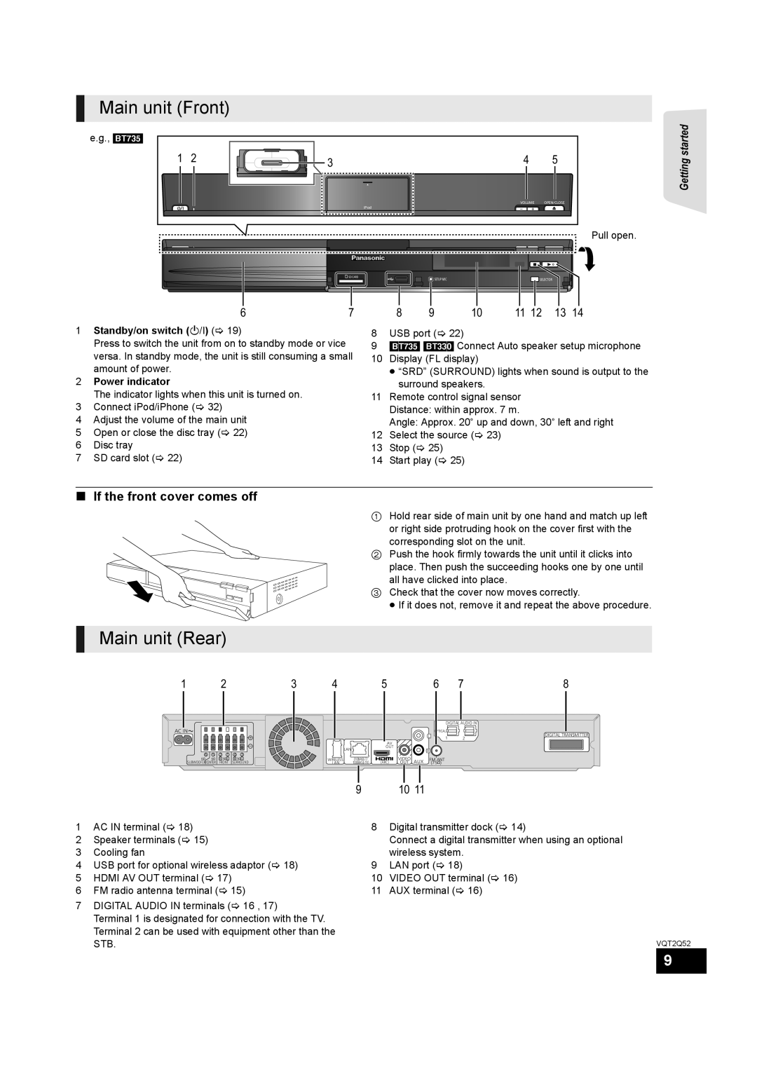
Main unit (Front)
e.g., [BT735]
1 2
3 |
iPod |
45
VOLUME OPEN/CLOSE
Pull open.
Getting started
SD CARD | SETUP MIC | SELECTOR |
|
67
1Standby/on switch (Í/I) (> 19)
Press to switch the unit from on to standby mode or vice versa. In standby mode, the unit is still consuming a small amount of power.
2Power indicator
The indicator lights when this unit is turned on.
3Connect iPod/iPhone (> 32)
4Adjust the volume of the main unit
5Open or close the disc tray (> 22)
6Disc tray
7SD card slot (> 22)
8 | 9 | 10 | 11 12 | 13 | 14 |
8USB port (> 22)
9[BT735] [BT330] Connect Auto speaker setup microphone
10Display (FL display)
≥“SRD” (SURROUND) lights when sound is output to the surround speakers.
11Remote control signal sensor Distance: within approx. 7 m.
Angle: Approx. 20e up and down, 30e left and right
12Select the source (> 23)
13Stop (> 25)
14Start play (> 25)
∫If the front cover comes off
1 Hold rear side of main unit by one hand and match up left or right side protruding hook on the cover first with the corresponding slot on the unit.
2 Push the hook firmly towards the unit until it clicks into place. Then push the succeeding hooks one by one until all have clicked into place.
3 Check that the cover now moves correctly.
≥ If it does not, remove it and repeat the above procedure.
Main unit (Rear)
1 | 2 | 3 | 4 | 5 | 6 | 7 | 8 |
AC IN ![]()
6 5
6Ω 6Ω SUBWOOFER CENTER
![]()
![]()
![]()
![]()
![]()
![]()
![]()
![]()
![]()
![]()
![]()
![]()
![]()
![]()
![]()
![]()
![]()
![]()
![]()
![]()
2 | 1 | 4 | 3 |
R 3Ω L | R 3Ω L | ||
FRONT | SURROUND | ||
DIGITAL AUDIO IN
| OPTICAL |
|
L | 1 | 2 |
|
|
| AV |
|
|
|
| LAN | OUT |
|
|
|
|
|
|
| R | |
WIRELESS | (ARC) | VIDEO | AUX | FM ANT | |
LAN | OUT | (75Ω) |
DIGITAL TRANSMITTER
1AC IN terminal (> 18)
2Speaker terminals (> 15)
3Cooling fan
4USB port for optional wireless adaptor (> 18)
5HDMI AV OUT terminal (> 17)
6FM radio antenna terminal (> 15)
7DIGITAL AUDIO IN terminals (> 16 , 17)
Terminal 1 is designated for connection with the TV. Terminal 2 can be used with equipment other than the STB.
910 11
8Digital transmitter dock (> 14)
Connect a digital transmitter when using an optional wireless system.
9LAN port (> 18)
10VIDEO OUT terminal (> 16)
11AUX terminal (> 16)
VQT2Q52
9