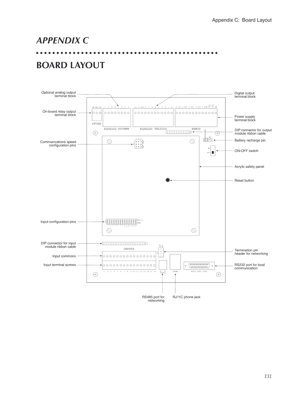
5000, 5100 specifications
Phonetics 5100 and 5000 represent advanced technology in the realm of communication devices tailored for enhancing auditory experiences through innovative phonetic design. These devices cater to individuals needing auditory assistance, offering features that improve sound clarity and reduce background noise while maintaining a comfortable listening experience.At the core of both Phonetics 5100 and 5000 are cutting-edge signal processing technologies that enable real-time sound adjustments. This technology allows users to experience tailored sound profiles based on their specific hearing needs or preferences. The devices utilize advanced microphone arrays, which capture sound from various directions, ensuring a 360-degree sound experience. This array not only enhances speech recognition but also filters out unwanted noise, providing a more focused listening environment.
Additionally, both models incorporate artificial intelligence algorithms that learn from the user’s listening habits. This feature allows the devices to automatically adjust settings based on the environments they are frequently used in, such as quiet rooms or bustling outdoor settings. The result is a seamless auditory experience that adapts to the ever-changing acoustic challenges of daily life.
Connectivity options are another significant aspect of the Phonetics 5100 and 5000. Both devices support Bluetooth technology, enabling users to connect them easily to smartphones, televisions, and other audio sources. This capability allows for direct streaming of phone calls and music, enhancing the versatility of the devices. The intuitive companion mobile app allows users to further customize audio settings and manage their device preferences with ease.
The design of the Phonetics 5100 and 5000 also focuses on user comfort and discretion. With a sleek, modern appearance, these devices prioritize aesthetics while ensuring that users feel confident and stylish while wearing them. Lightweight materials and ergonomic designs make them comfortable for extended use.
In summary, Phonetics 5100 and 5000 are robust auditory assistance devices renowned for their innovative sound processing capabilities, user-friendly interfaces, artificial intelligence integration, and stylish comfort. They stand at the forefront of the audiology field, ensuring that users can engage fully in their auditory world.

