33
System Interconnect Diagram
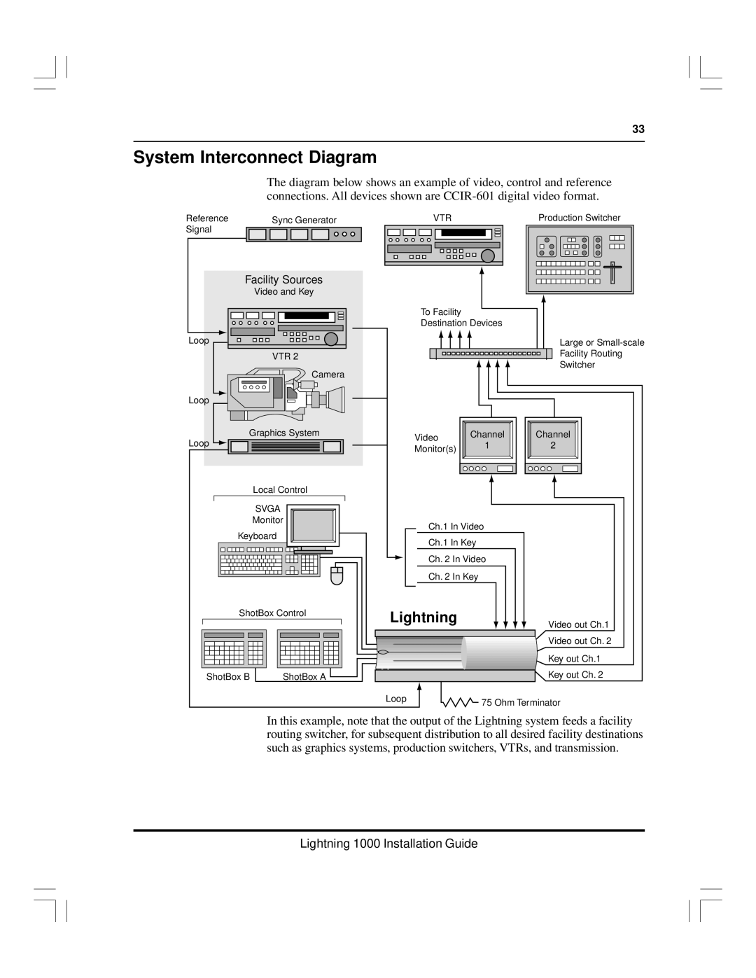
The diagram below shows an example of video, control and reference connections. All devices shown are
Reference |
| Sync Generator |
|
|
|
|
| VTR |
|
|
|
| Production Switcher | ||||||||||||||||||||||||||||||||||
Signal |
|
|
|
|
|
|
|
|
|
|
|
|
|
|
|
|
|
|
|
|
|
|
|
|
|
|
|
|
|
|
|
|
|
|
|
|
|
|
|
|
|
|
|
|
|
| |
|
|
|
|
|
|
|
|
|
|
|
|
|
|
|
|
|
|
|
|
|
|
|
|
|
|
|
|
|
|
|
|
|
|
|
|
|
|
|
|
|
|
|
|
|
|
|
|
|
|
|
|
|
|
|
|
|
|
|
|
|
|
|
|
|
|
|
|
|
|
|
|
|
|
|
|
|
|
|
|
|
|
|
|
|
|
|
|
|
|
|
|
|
|
|
|
|
|
|
|
|
|
|
|
|
|
|
|
|
|
|
|
|
|
|
|
|
|
|
|
|
|
|
|
|
|
|
|
|
|
|
|
|
|
|
|
|
|
|
|
|
|
|
|
|
|
|
|
|
|
|
|
|
|
|
|
|
|
|
|
|
|
|
|
|
|
|
|
|
|
|
|
|
|
|
|
|
|
|
|
|
|
|
|
|
|
|
|
|
|
|
|
|
|
|
|
|
|
|
|
|
|
|
|
|
|
|
|
|
|
|
|
|
|
|
|
|
|
|
|
|
|
|
|
|
|
|
|
|
|
|
|
|
|
|
|
|
|
|
|
Facility Sources
Video and Key
Loop
VTR 2
Camera
Loop
Graphics System
Loop ![]()
![]()
![]()
Local Control
SVGA
Monitor
Keyboard
ShotBox Control | |
ShotBox B | ShotBox A |
To Facility
Destination Devices
Large or
Facility Routing
Switcher
Video | Channel | Channel | |
1 | 2 | ||
Monitor(s) | |||
|
|
Ch.1 In Video
Ch.1 In Key
Ch. 2 In Video
Ch. 2 In Key
Lightning
Video out Ch.1
Video out Ch. 2
Key out Ch.1
Key out Ch. 2
Loop | 75 Ohm Terminator |
|
In this example, note that the output of the Lightning system feeds a facility routing switcher, for subsequent distribution to all desired facility destinations such as graphics systems, production switchers, VTRs, and transmission.