31
Automation Systems Connections
Ports
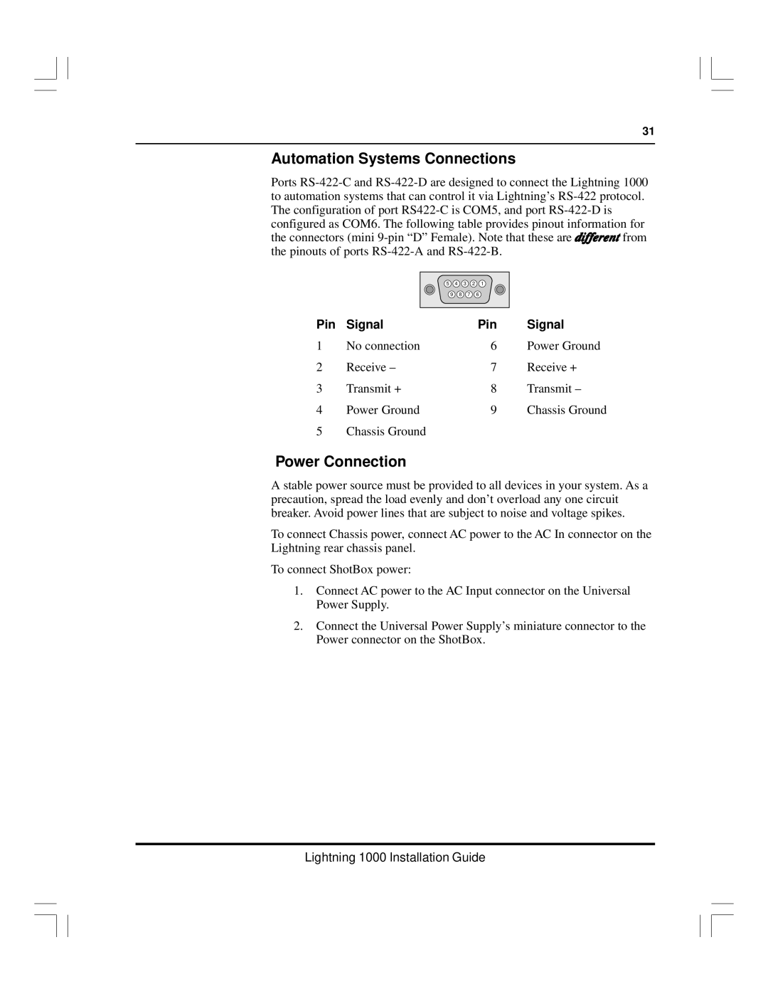
5 | 4 | 3 | 2 | 1 |
9 | 8 | 7 |
| 6 |
Pin | Signal | Pin | Signal |
1 | No connection | 6 | Power Ground |
2 | Receive – | 7 | Receive + |
3 | Transmit + | 8 | Transmit – |
4 | Power Ground | 9 | Chassis Ground |
5 | Chassis Ground |
|
|
Power Connection
A stable power source must be provided to all devices in your system. As a precaution, spread the load evenly and don’t overload any one circuit breaker. Avoid power lines that are subject to noise and voltage spikes.
To connect Chassis power, connect AC power to the AC In connector on the Lightning rear chassis panel.
To connect ShotBox power:
1.Connect AC power to the AC Input connector on the Universal Power Supply.
2.Connect the Universal Power Supply’s miniature connector to the Power connector on the ShotBox.