13
Chassis Rear Panel Components
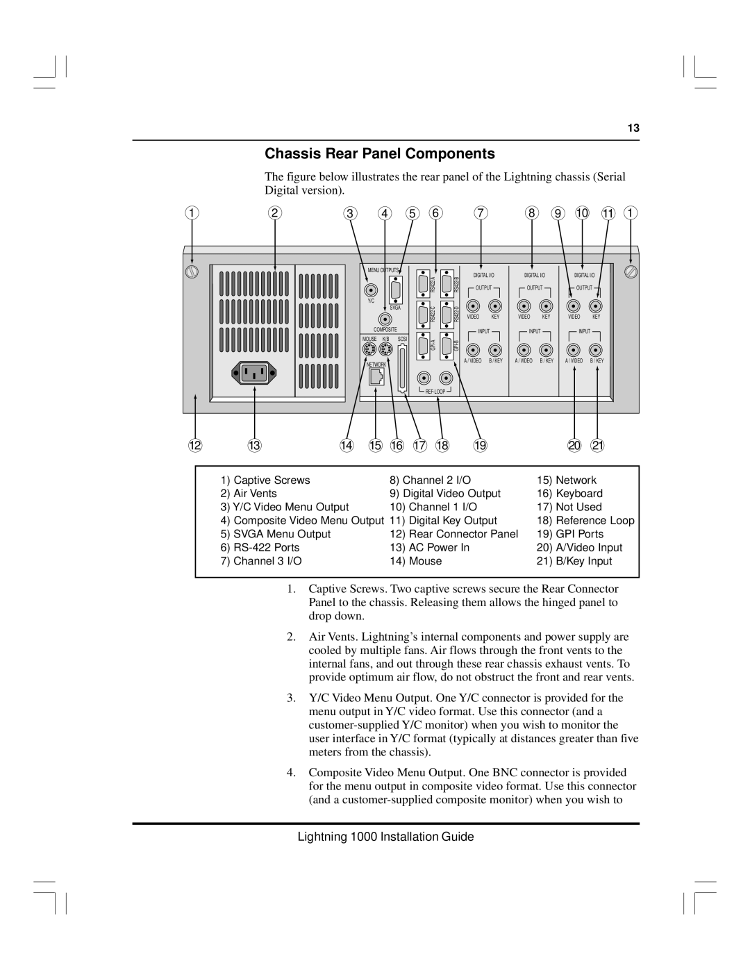
The figure below illustrates the rear panel of the Lightning chassis (Serial Digital version).
1 | 2 | 3 | 4 |
| 5 | 6 |
| 7 |
| 8 | 9 | 10 | 11 | 1 |
|
|
| MENU OUTPUTS |
|
|
| DIGITAL I/O | DIGITAL I/O | DIGITAL I/O |
| ||||
|
|
|
|
|
| A | B |
| ||||||
|
|
|
|
|
| - | - |
|
|
|
|
|
|
|
|
|
|
|
|
| RS422 | RS422 | OUTPUT | OUTPUT | OUTPUT |
| |||
|
|
| Y/C |
|
|
|
|
|
|
|
|
|
|
|
|
|
|
| SVGA |
|
|
|
|
|
|
|
| ||
|
|
|
|
|
| RS422 | RS422 | VIDEO | KEY | VIDEO | KEY | VIDEO | KEY |
|
|
|
|
|
|
|
|
|
|
|
|
|
| ||
|
|
| COMPOSITE |
|
|
| INPUT | INPUT | INPUT |
|
| |||
|
|
|
|
|
|
|
|
|
| |||||
|
|
| MOUSE K/B | SCSI |
|
|
|
|
|
|
|
| ||
|
|
|
|
|
|
|
|
|
|
|
|
| ||
|
|
| NETWORK |
|
|
|
| A / VIDEO | B / KEY | A / VIDEO | B / KEY | A / VIDEO | B / KEY |
|
|
|
|
|
|
|
|
|
|
|
|
|
|
| |
|
|
|
|
|
|
|
|
|
|
|
|
|
| |
12 | 13 | 14 | 15 | 16 | 17 | 18 |
| 19 |
|
|
| 20 | 21 |
|
1) | Captive Screws | 8) Channel 2 I/O | 15) | Network | |
2) | Air Vents | 9) Digital Video Output | 16) Keyboard | ||
3) Y/C Video Menu Output | 10) | Channel 1 I/O | 17) | Not Used | |
4) | Composite Video Menu Output 11) | Digital Key Output | 18) | Reference Loop | |
5) | SVGA Menu Output | 12) | Rear Connector Panel | 19) | GPI Ports |
6) | 13) | AC Power In | 20) | A/Video Input | |
7) | Channel 3 I/O | 14) | Mouse | 21) | B/Key Input |
1.Captive Screws. Two captive screws secure the Rear Connector Panel to the chassis. Releasing them allows the hinged panel to drop down.
2.Air Vents. Lightning’s internal components and power supply are cooled by multiple fans. Air flows through the front vents to the internal fans, and out through these rear chassis exhaust vents. To provide optimum air flow, do not obstruct the front and rear vents.
3.Y/C Video Menu Output. One Y/C connector is provided for the menu output in Y/C video format. Use this connector (and a
4.Composite Video Menu Output. One BNC connector is provided for the menu output in composite video format. Use this connector (and a
Lightning 1000 Installation Guide