Connecting the System
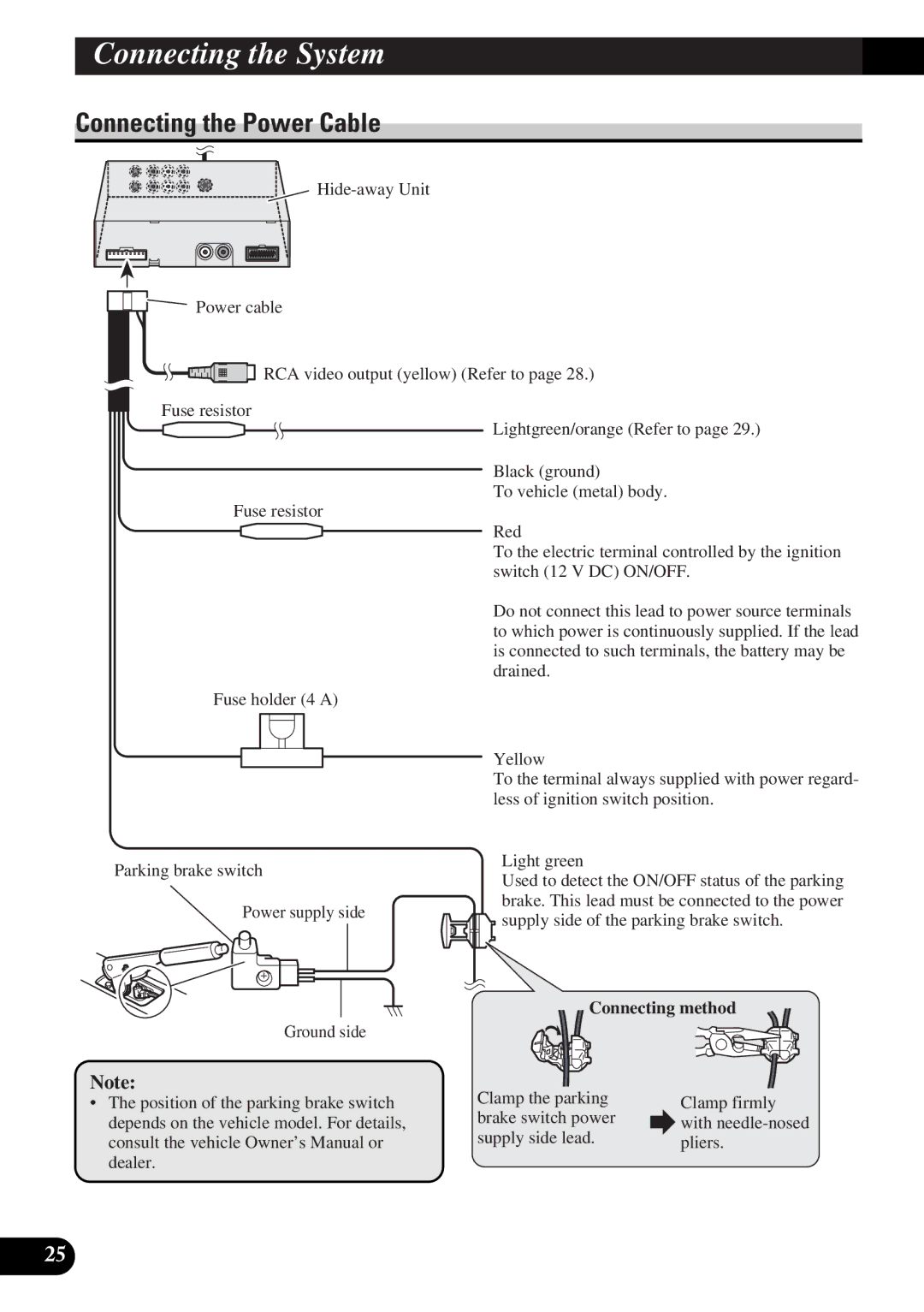
Connecting the Power Cable
Power cable
![]() RCA video output (yellow) (Refer to page 28.)
RCA video output (yellow) (Refer to page 28.)
Fuse resistor
Lightgreen/orange (Refer to page 29.)
Black (ground)
To vehicle (metal) body.
Fuse resistor
Red
To the electric terminal controlled by the ignition switch (12 V DC) ON/OFF.
Do not connect this lead to power source terminals to which power is continuously supplied. If the lead is connected to such terminals, the battery may be drained.
Fuse holder (4 A)
Yellow
To the terminal always supplied with power regard- less of ignition switch position.
Parking brake switch
Power supply side
Light green
Used to detect the ON/OFF status of the parking brake. This lead must be connected to the power ![]() supply side of the parking brake switch.
supply side of the parking brake switch.
Ground side
Note:
•The position of the parking brake switch depends on the vehicle model. For details, consult the vehicle Owner’s Manual or dealer.
Connecting method
Clamp the parking | Clamp firmly | |
brake switch power | ||
with | ||
supply side lead. | ||
pliers. | ||
|
25
