Using with other equipment
Specifying the type of digital video signals
1Press HOME MENU.
2Select “Option” (/ then ENTER).
3Select “HDMI Input” (/ then ENTER).
4Select “Video“ (/ then ENTER).
5Select the type of digital video signals (/ then ENTER).
•If you select “Auto”, an attempt will be made to identify the type of digital video signals when digital video signals are received.
Item | Description |
Auto (default) | Automatically identifies input digital video signals |
|
|
Digital Component Video signals (4:2:2) locked | |
|
|
Digital Component Video signals (4:4:4) locked | |
|
|
Digital RGB signals (16 to 235) locked | |
|
|
Digital RGB signals (0 to 255) locked | |
|
|
6 Press HOME MENU to exit the menu.
![]() Note
Note
•If you select a parameter other than “Auto”, make such a setting that results in natural color.
•If no image appears, or images appear in inappropriate colors, specify another digital video signal type.
•For the digital video signal types to be specified, check the operation manual that came with the connected equipment.
Specifying the type of audio signals
When using the INPUT 3 HDMI terminal, you need to specify the type of audio signals.
1Repeat steps 1 to 3 provided for Specifying the type of digital video signals.
2Select “Audio“ (/ then ENTER).
3Select the type of audio signals (/ then ENTER).
•If you select “Auto”, an attempt will be made to identify the type of audio signals when audio signals are received.
Item | Description |
Auto (default) | Automatically identifies the input signals |
|
|
Digital | Accepts digital audio signals |
|
|
Analog | Accepts analog audio signals |
|
|
4 Press HOME MENU to exit the menu.
![]() Note
Note
•The INPUT 4 and INPUT 5 HDMI terminals accept only digital audio signals.
•If no sound is output, specify another audio signal type.
•For the audio signal types to be specified, check the operation manual that came with the connected equipment.
•Depending on the equipment to be connected, you also need to connect analog audio cables.
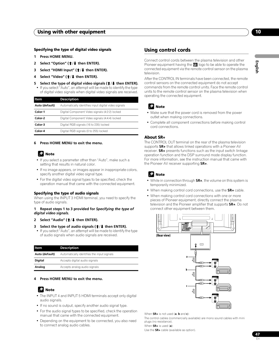
Using control cords
Connect control cords between the plasma television and other Pioneer equipment having the tlogo to be able to operate the connected equipment via the remote control sensor on the plasma television.
After the CONTROL IN terminals have been connected, the remote control sensors on the connected equipment do not accept commands from the remote control units. Face the remote control units to the remote control sensor on the plasma television when operating the connected equipment.
![]() Note
Note
•Make sure that the power cord is removed from the power outlet when making connections.
•Complete all component connections before making control cord connections.
About SR+
The CONTROL OUT terminal on the rear of the plasma television supports SR+ that allows linked operations with a Pioneer AV receiver. SR+ presents functions such as the input switch linkage operation function and the DSP surround mode display function. For more information, see the instruction manual that came with the Pioneer AV receiver supporting SR+.
![]() Note
Note
•While in connection through SR+, the volume on this system is temporarily minimized.
•When making control cord connections, use the SR+ cable.
•When making control cord connections with one or more pieces of Pioneer equipment, directly connect the plasma television and the Pioneer amplifier that supports SR+. Do not connect other equipment between them.
(Rear view)
a
CONTROL
IN
OUT
b
CONTROL
IN
OUT
c
CONTROL
IN
OUT
When SR+ is not used (a, b and c):
The control cables (commercially available) are mono sound cables with mini plugs (no resistance).
When SR+ is used (a):
Use the SR+ cable (available as option).
10
English
47
En