Manuals
/
Pioneer
/
Home Audio
/
Stereo Amplifier
Pioneer
PRS-A900
owner manual
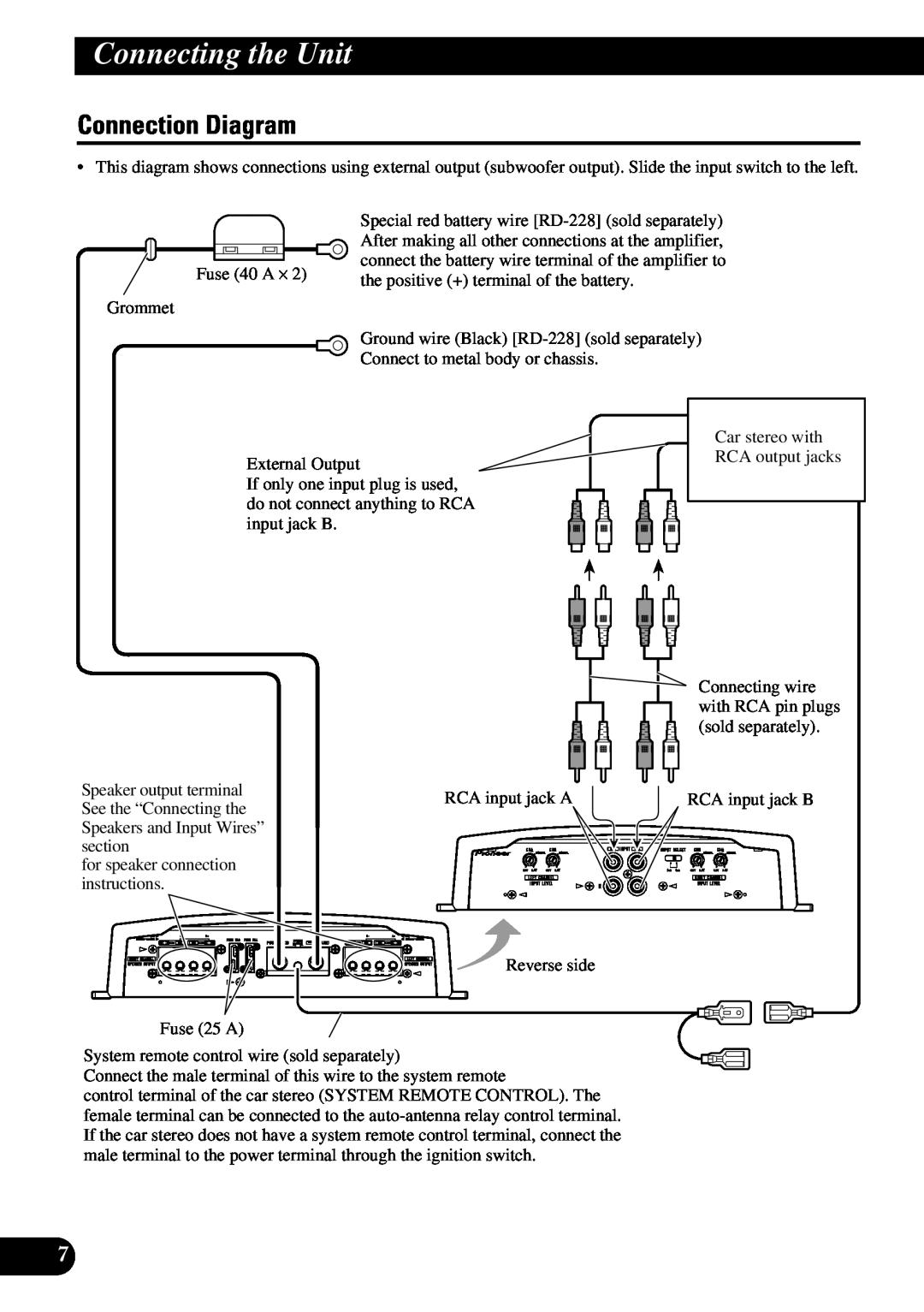
Connection Diagram, Connecting the Unit
Models:
PRS-A900
1
8
100
100
Download
100 pages
22.57 Kb
5
6
7
8
9
10
11
12
Specifications
Install
Connection Diagram
Étiquette signalétique
Power Indicator
Connecting the Unit
Bij problemen
Setting the Unit
Connecting the Power Terminal
Page 8
Image 8
Page 7
Page 9
Page 8
Image 8
Page 7
Page 9
Contents
óÖíõêÖïäÄçÄãúçõâ ìëàãàíÖãú åéôçéëíà BRIDGEABLE
êìëëäàâ
BRIDGEABLE FOUR-CHANNELPOWER AMPLIFIER
PRS-A900
Contents
Before Using This Product
Visit our website
Installation
In case of trouble
Setting the Unit
BFC Beat Frequency Control Switch
Power Indicator
Input Select Switch
Terminal Cover
Setting the Gain properly
amplifier and the output power of the head unit
Signal waveform when outputting at high
Relationship between the gain of the
Connecting the Unit
ENGLISH ESPAÑOL DEUTSCH
To prevent damage and/or injury
FRANÇAIS ITALIANO NEDERLANDS
Connection Diagram
Connecting the Unit
Connecting the Speaker Output Terminals
Solderless Terminal Connections
Connecting the Speakers and Input Wires
Four-channelmode
Three-channelmode
Connecting the Unit
Two-channelmode Stereo
ENGLISH ESPAÑOL DEUTSCH FRANÇAIS
Two-channelmode Mono
ITALIANO NEDERLANDS êìëëäàâ
Connecting the Power Terminal
Connecting the Unit
Installation
To prevent malfunction and/or injury
Installation
Replacing the terminal cover
Changing the Direction of the Badge
Specifications
Average current drawn
Contenido
Antes de usar este producto
Visite nuestro sitio Web
Instalación
En caso de desperfectos
PRECAUCION
ADVERTENCIA
PRECAUCION
Ajuste de esta unidad
Cubierta de terminales
Placa de identificación
Indicador de alimentación
Interruptor de selección de entrada
Configuración apropiada de la ganancia
volumen alto por el control de ganancia
Relación entre la ganancia del amplifi
principal
Conexión de la unidad
PRECAUCION
ENGLISH ESPAÑOL
PRECAUCION Para evitar daños y/o lesiones
Diagrama de conexión
Conexión de la unidad
Conexiones de terminales sin sol- dadura
Conexión del terminal de salida de altavoz
Conexión de los altavoces y cables de entrada
Modo de cuatro canales
Modo de tres canales
Conexión de la unidad
Modo de dos canales estéreo
Modo de dos canales mono
ENGLISH ESPAÑOL DEUTSCH FRANÇAIS ITALIANO
êìëëäàâ
Conexión de la unidad
Conexión del terminal de alimentación
ADVERTENCIA
Instalación
Para evitar fallas de funcionamiento y/o lesiones
PRECAUCION
PRECAUCION
Recolocación de la cubierta de terminales
Instalación
Alfombra
del piso o
Consumo de corriente promedio
Especificaciones
Nota
Inhaltsverzeichnis
Vor Gebrauch dieses Produkts
Unsere Website
Einbau
Im Störungsfall
VORSICHT
WARNUNG
Diagramm A - Richtig
Einstellen dieses Geräts
Anschlussabdeckung
Plakette
Interferenzschutzschalter BFC
Stromanzeige
Signal-Wellenformbei Klangwiedergabe
Richtige Einstellung der Verstärkung
Beziehung zwischen
Leistungsverstärkung des Verstärkers
Anschluss der Einheit
VORSICHT
Zur Vermeidung von Schäden und/oder Verletzungen
VORSICHT
Anschlussschema
Anschluss der Einheit
Lötfreie Verbindungen
Anschluss der Lautsprecher- Ausgang-Klemmen
Anschluss der Lautsprecher und Eingangskabel
Vier-Kanal-Modus
Drei-Kanal-Modus
Anschluss der Einheit
Zwei-Kanal-ModusStereo
Zwei-Kanal-ModusMono
ENGLISH ESPAÑOL DEUTSCH FRANÇAIS
ITALIANO NEDERLANDS êìëëäàâ
Anschluss der Einheit
Anschluss der Stromversorgung
WARNUNG
VORSICHT
Einbau
VORSICHT
Einbau
Wiederanbringen der Anschlussabdeckung
Ändern der Ausrichtung der Plakette
Durchschnittliche Stromentnahme
Technische Daten
Hinweis
Table des matières
Avant d’utiliser cet appareil
Visitez notre site Web
Installation
PRÉCAUTION
En cas d’anomalie
PRÉCAUTION
Réglage de l’appareil
Étiquette signalétique
Commande du gain
Couvre-bornes
Témoin d’alimentation
Commande du gain de cet appareil
Forme de signal quand la puissance de
Réglage correct du gain
Relation entre le gain de l’amplificateur
Raccordement de l’appareil
PRÉCAUTION
PRÉCAUTION Pour éviter toute anomalie ou blessure
ENGLISH ESPAÑOL DEUTSCH
Schéma de raccordement
Raccordement de l’appareil
Prise de connexion sans soudure
Raccordement des haut-parleurset des câbles
Mode quatre voies
Mode trois voies
Raccordement de l’appareil
1053
Mode deux voies stéréo
Mode deux voies mono
Raccordement de la borne d’alimentation
Raccordement de l’appareil
Installation
N’installez pas l’appareil
PRÉCAUTION
PRÉCAUTION
Remise en place du couvre-bornes
Installation
Consommation moyenne de courant
Caractéristiques techniques
Remarque
Indice
Prima di usare questo prodotto
Visita il nostro sito Web
Installazione
In caso di difficotà
PRECAUZIONE
ATTENZIONE
PRECAUZIONE
Regolazione di questa unità
Indicatore dell’alimentazione
Coperchio dei terminali
Etichetta
Selettore BFC Beat Frequency Control
Regolazione corretta del guadagno
Relazione tra il guadagno
dell’amplificatore e la potenza di uscita
dell’unità principale
Come collegare l’unità
PRECAUZIONE
Per evitare danneggiamenti e/o lesioni
ENGLISH ESPAÑOL
Schema di collegamento
Come collegare l’unità
Collegamenti senza saldatura ai terminali
Come collegare l’unità
Modo a quattro canali
Modo a tre canali
Modo a due canali stereo
Modo a due canali mono
Come collegare il terminale dell’alimentazione
ATTENZIONE
Come collegare l’unità
2.Collegare i cavi al morsetto
Installazione
PRECAUZIONE
PRECAUZIONE
Per evitare malfunzionamenti e/o lesioni
Installazione
Riapplicazione del coperchio dei terminali
Cambio di orientamento dell’etichetta
Corrente media consumata
Caratteristiche
Nota
Inhoudsopgave
Alvorens gebruik
Bezoek onze website
Installatie
Bij problemen
WAARSCHUWING
WAARSCHUWING
WAARSCHUWING
Instellen van dit toestel
Spanningsindicator
Aansluitingenafdekking
Embleem
BFC Beat Frequency Control schakelaar
volume via de ‘gain’ instelling van de versterker
Correct instellen van de Gain extra versterking
‘Gain’ instelling van dit toestel
Verhouding tussen de ‘gain’ van de
Aansluiten van het toestel
WAARSCHUWING
FRANÇAIS ITALIANO
ENGLISH ESPAÑOL DEUTSCH
Aansluitschema
Aansluiten van het toestel
Aansluitingen zonder solderen
Verbinden van de luidsprekeruitgangsaansluitingen
Aansluiten van de luidsprekers en ingangssnoeren
Vier-kanalenfunctie
Drie-kanalenfunctie
Aansluiten van het toestel
Twee-kanalenfunctie stereo
Twee-kanalenfunctie mono
ENGLISH ESPAÑOL DEUTSCH FRANÇAIS
ITALIANO NEDERLANDS êìëëäàâ
WAARSCHUWING
Aansluiten van het spanningsaansluitpunt
Aansluiten van het toestel
Installatie
Om slechte werking en/of letsel te voorkomen
WAARSCHUWING
WAARSCHUWING
Installatie
Omdraaien van het embleem
Terugzetten van de aansluitingenafdekking
Gemiddeld stroomverbruik
Technische gegevens
Opmerking
ëÓ‰ÂʇÌËÂ
àÌÒÚÛ͈ËË Ô‰ ̇˜‡ÎÓÏ
˝ÍÒÔÎÛ‡Ú‡ˆËË ‰‡ÌÌÓ„Ó ÛÒÚÓÈÒÚ‚‡
èÓÒÂÚËÚ ̇¯ Ò‡ÈÚ
éëíéêéÜçé
èêÖÑìèêÖÜÑÖçàÖ
ç‡ÒÚÓÈ͇ ÛÒÚÓÈÒÚ‚‡
ä˚¯Í‡
ùÏ·ÎÂχ
èÂÂÍβ˜‡ÚÂθ BFC ÔÂÂÍβ˜‡ÚÂθ ˜‡ÒÚÓÚ˚ ·ËÂÌËfl
à̉Ë͇ÚÓ ÔËÚ‡ÌËfl
ê„ÛÎËÓ‚‡ÌË ìÒËÎÂÌËfl ‰ÓÎÊÌ˚Ï Ó·‡ÁÓÏ
ç‡ÒÚÓÈ͇ ÛÒÚÓÈÒÚ‚‡
äÓÌÚÓθ ÛÒËÎÂÌËfl ‰‡ÌÌÓ„Ó ÔË·Ó‡
‚˚ıÓ‰ÌÓÈ ÏÓ˘ÌÓÒÚ¸˛ ÒËÎÓ‚ÓÈ „ÓÎÓ‚ÍË
èÓ‰Íβ˜ÂÌË ÛÒÚÓÈÒÚ‚‡
DEUTSCH FRANÇAIS ITALIANO
ENGLISH ESPAÑOL
ä‡Ì‡Î ‰Ë̇ÏË͇
ëıÂχ ÒÓ‰ËÌÂÌËÈ
èÓ‰Íβ˜ÂÌË ÛÒÚÓÈÒÚ‚‡
ëÓ‰ËÌÂÌËfl ·ÂÒԇ˜Ì˚ı ÍÎÂÏÏ
ëÓ‰ËÌÂÌË ‚˚ıÓ‰Ì˚ı Á‡ÊËÏÓ‚ ‰Ë̇ÏË͇
ÇËÌÚÓ‚ÓÈ Á‡ÊËÏ èÓ‚Ó‰ ‰Ë̇ÏË͇ Ç˚ıÓ‰ÌÓÈ Á‡ÊËÏ
‰Ë̇ÏË͇
èÓ‰Íβ˜ÂÌË ‰Ë̇ÏËÍÓ‚ Ë ‚˚ıÓ‰Ì˚ı ÔÓ‚Ó‰Ó‚
èÓ‰Íβ˜ÂÌË ÛÒÚÓÈÒÚ‚‡
óÂÚ˚Âı͇̇θÌ˚È ÂÊËÏ
íÂı͇̇θÌ˚È ÂÊËÏ
Ñ‚Ûı͇̇θÌ˚È ÂÊËÏ ÒÚÂÂÓ
Ñ‚Ûı͇̇θÌ˚È ÂÊËÏÏÓÌÓ
ENGLISH ESPAÑOL DEUTSCH FRANÇAIS ITALIANO
êìëëäàâ
èÓ‰Íβ˜ÂÌË ÛÒÚÓÈÒÚ‚‡
ëÓ‰ËÌÂÌË ÍÎÂÏÏ˚ ËÒÚÓ˜ÌË͇ ÔËÚ‡ÌËfl
éëíéêéÜçé
ìÒÚ‡Ìӂ͇
éëíéêéÜçé
ìÒÚ‡Ìӂ͇
ÇÓÁ‚‡˘ÂÌË Í˚¯ÍË Ì‡ ÏÂÒÚÓ
àÁÏÂÌÂÌË ç‡Ô‡‚ÎÂÌËfl ùÏ·ÎÂÏ˚
ëÔˆËÙË͇ˆËË
èËϘ‡ÌËÂ
èËϘ‡ÌËÂ
ë‰Ì ÔÓÚ·ÎÂÌË ÚÓ͇
PIONEER CORPORATION
äÓÔÓ‡ˆËfl è‡ÈÓÌË
<KOKNX> <07I00000>
PIONEER ELECTRONICS USA INC
Top
Page
Image
Contents