Manuals
/
Pioneer
/
Home Audio
/
Stereo Amplifier
Pioneer
RS-A9/EW
manual
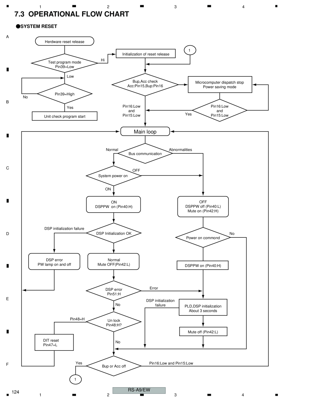
Operational Flow Chart, Main loop, Systemreset
Models:
RS-A9/EW
1
124
128
128
Download
128 pages
2.31 Kb
121
122
123
124
125
126
127
128
Specs
Parts list
Block Diagram
Circuit Symbol and No
Systemreset
Disassembly
Audio Unit Adjustment
Setting Example
Service Precaution
Switch Pcb
Page 124
Image 124
Page 123
Page 125
Page 124
Image 124
Page 123
Page 125
Contents
CRT3232
RS-A9/EW
SAFETY INFORMATION
Service Precaution
CONTENTS
1. SPECIFICATIONS
POWER AMP
GENERAL
BDSP/PREAMP
RS-A9/EW
A B C D E F
2.1 PACKING
2. EXPLODED VIEWS AND PARTS LIST
Part No
Language
Mark No
Description
2.2 EXTERIOR
Mark No
Description
Part No
Description
3. BLOCK DIAGRAM AND SCHEMATIC DIAGRAM
3.1 BLOCK DIAGRAM
RS-A9/EW
RS-A9/EW
RS-A9/EW
3.2 AMP UNITGUIDE PAGE
Guide page
RS-A9/EW
PCB CONTROL C CN201 RS-A9/EW
CN901
RS-A9/EW
16dBs
14dBs
AMP UNIT
CEK1139
FU1902
PCB CONTROL C
RS-A9/EW
CEK1139 > FU1903
5 CN901 6
5 6 7
B1/2
B-a 1/2
3.3 DSP UNITDACGUIDE PAGE
B 2/2
B-b 1/2
B 1/2
B 2/2
B 1/2
B-b 1/2
B-a 1/2
RS-A9/EW
C CN308
B-b 1/2
B-a 1/2
B 2/2
B 2/2
B-b 1/2
B 1/2
UNITDACDSP
opposition
B-b 1/2
RS-A9/EW
B2/2
B-a 2/2
3.4 DSP UNITDSPGUIDE PAGE
B 1/2
B-b 2/2
B 2/2
B 2/2
B 1/2
B-b 2/2
B-a 2/2
RS-A9/EW
B 1/2
B-a 2/2
B-b 2/2
RS-A9/EW
B-b 2/2
For JTAG
B 2/2
BUNITDSP DSP
B-b 2/2
RS-A9/EW
DSP2 LOGIC
DSP1 LOGIC
D CN
3.5 CONTROL UNITGUIDE PAGE
RS-A9/EW
RS-A9/EW
C-b1
C-aE F H
USB PCB
IPIN PCB
C-a G H
H IPOUT PCB
Ach PCB
PCB SW
CONTROLPCB
CN2281
RS-A9/EW
3.6 SWITCH PCB
SWITCH PCB
RS-A9/EW
A B C D E F
A AMP UNIT
NOTE FOR PCB DIAGRAMS
SIDE A
AMP UNIT
RS-A9/EW
SIDE A
C CN901
RS-A9/EW
C CN201
CN901
RS-A9/EW
C D E F
A AMP UNIT
RS-A9/EW
SIDE B
RS-A9/EW
EUNIT AMP
RS-A9/EW
SIDE B
RS-A9/EW
RS-A9/EW
4.2 DSP UNITGUIDE PAGE
B DSP UNIT
C CN101
SIDE A
RS-A9/EW
IC,Q
CN308
EUNIT DSP
CN601
RS-A9/EW
CN601
BA-a B-b
C CN801
CN101
SIDE A
RS-A9/EW
CN801
RS-A9/EW
IC,Q
B DSP UNIT
RS-A9/EW
SIDE B
RS-A9/EW
DSP UNIT
RS-A9/EW
RS-A9/EW
SIDE
RS-A9/EW
RS-A9/EW
4.3 CONTROL PCBGUIDE PAGE
CONTROL PCB
N513
H CN511
I CN501
J CN503
EPCB CONTROL
CN513
CN509
CN507
CN1102
CN1904
CN3201
CN401
CN2401
CN505
CN503
CN501
CN2281
CN2401
CN1102
RS-A9/EW
IC,Q
C CONTROL PCB
RS-A9/EW
SIDE B
RS-A9/EW
CONTROL PCB
RS-A9/EW
RS-A9/EW
SIDE B
RS-A9/EW
RS-A9/EW
4.4 SWITCH PCB
AD SWITCH PCB
D SWITCH PCB
SIDE A
4.5 USB PCB AND IPIN PCB
E USB PCB USB
E USB PCB
F IPIN PCB IP-BUSIN
4.6 Ach PCB AND IPOUT PCB
G Ach PCB
Ach OPT IN1
H IPOUT PCB
4.7 SW PCB AND LOW PCB
I SW PCB SW OPT-OUT
I SW PCB
J LOW PCB LOW OPT-OUT
4.8 MID PCB
K MID PCB
MID OPT-OUT
K MID PCB
5. ELECTRICAL PARTS LIST
Unit Number:CWH1264 Unit Name:Amp Unit
Chip Resistor RS1/_S___J,RS1/__S___J
Chip Capacitor except for CQS
Circuit Symbol and No
Circuit Symbol and No
Part No
Part No
RS-A9/EW
Unit Number:CWX3066
Unit Name:DSP Unit
RS-A9/EW
1234
RS-A9/EW
RN1/16SC47R0D
RS-A9/EW
6.2 AUDIO UNIT ADJUSTMENT
RS-A7/EW
RS-A9/EW
RS-A7/EW
RS-A9/EW
RS-A9/EW
RS-A9/EW
CKSRYB104K16
CDEFGHIJK
Unit Number:CWM9586 Unit Name:Control Unit
1234
RS-A9/EW
RS-A9/EW
RS-A9/EW
6. ADJUSTMENT
6.1 AMP UNIT ADJUSTMENT
RS-A9/EW
TEST POINT
SIDE A SIDE B
6.2 DSP UNIT ADJUSTMENT
RS-A9/EW
Connecting Diagram for DSP Unit Offset Voltage
Master Clock
RS-A9/EW
TEST POINT
SIDE A
7. GENERAL INFORMATION
7.1.1 DISASSEMBLY
7.1 DIAGNOSIS
DSP/Control Unit Case
Removingthe Case Fig.4
Fig.4
Page
7.1.3 CONNECTOR FUNCTION DESCRIPTION
RS-A9/EW
1 2 3 4 5 6 7 8 9 10 11 12 13 14
7.2 IC
RS-A9/EW
RS-A9/EW
RS-A9/EW
TC7SZU04FU
OUTY
SM5849BF
Page
RS-A9/EW
NJM78L18UA
S-80827CNUA-B8M
NJM79L18UA
S-812C33AMC-C2N
Page
BUS+
DGND IOUT2C
IOUT1C RFB C VREF C IOUT2D IOUT1D RFB D VREF D
SDOUT CLR LDAC FSIN
28 27 26 25 24 23 22 21 20 19 18 17 16 15
Pin Functions PD5952A
Pin No
SYSTEMRESET
7.3 OPERATIONAL FLOW CHART
Main loop
8. OPERATIONS
Setting Example
Example of 2-waysystem connection with 1 RS-A9
Connection Diagram
RS-A9/EW
A B C D E F
Test Disc : YEDS-7
Jigs list
RS-A9/EW
Top
Page
Image
Contents