5 | 6 | 7 |
7. GENERAL INFORMATION
7.1 DIAGNOSIS
7.1.1 DISASSEMBLY
8
A
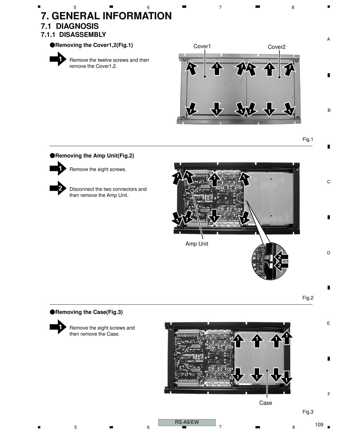
1Remove the twelve screws and then remove the Cover1,2.
Cover1
1 | 1 |
|
|
1 | 1 |
1
1
Cover2
1 | 1 | 1 |
|
|
|
1 | 1 | 1 | B |
Fig.1
1Remove the eight screws.
1 | 1 | 1 |
| ||
|
|
2Disconnect the two connectors and then remove the Amp Unit.
1 | 1 | 1 |
|
|
Amp Unit
1Remove the eight screws and then remove the Case.
1
1
1
1
C
D
2
2
Fig.2
E
1 | 1 | 1 |
| ||
1 | 1 | 1 |
|
|
F
Case
Fig.3
5 | 6 |
|
|
| 7 |
8
109