5 | 6 | 7 | 8 |
6.2 DSP UNIT ADJUSTMENT
The items for adjusting DSP unit are:
1Offset voltage
2Master clock
The adjustment for service should be served in the product condition, instead of in the unit condition. (Otherwise, it would require jigs.)
Both adjustments are capable by removing the bottom plate of product, the sealed case of Control Assy and black panel
Adjustment is done by using the following
For adjusting master clock
(Measuring instruments to be used)
For adjusting offset voltage: Voltage measuring device such as a
For adjusting master clock: Frequency counter or
(Adjustment Requirements)
Operate the product in the following requirements and make adjustment within 2 or 3 minutes from the start of such operation.
No. | Item | Rated Value | Requirements | |
|
|
|
|
|
1 | Offset Voltage | 0 Below | 10mV | Set volume value of Main Unit to - 72dB and |
|
|
|
| reproduce CD without recording. *1 |
|
|
|
|
|
2 | Master clock | 24.576MHz | 20Hz | Set volume value of Main Unit to - 72dB and |
|
|
|
| reproduce CD without recording. *1 |
|
|
|
|
|
*1 : 23 tracks of test
Sensing pin land of AL2 : its equivalent land and GND
Sensing pin land of AR2 : its equivalent land and GND
Sensing pin land of BL2 : its equivalent land and GND
Sensing pin land of BR2 : its equivalent land and GND
(The measuring points for adjusting master clock)
TP3001 or its equivalent land and TP3002 or its equivalent GND
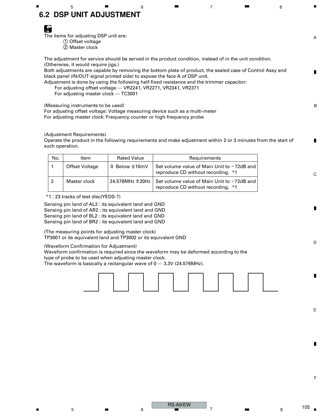
(Waveform Confirmation for Adjustment)
Waveform confirmation is required since the waveform may be deformed according to the type of probe to be used when adjusting master clock.
The waveform is basically a rectangular wave of 0
|
|
|
|
|
|
|
| |
|
|
|
| 105 | ||||
5 | 6 |
|
|
| 7 | 8 | ||
| ||||||||
A
B
C
D
E
F