ELECTRICAL CONNECTIONS
Electrical Shock Hazard Disconnect power before servicing.
Replace all parts and panels before operating.
Failure to do so can result in death or electrical shock.
If you lack the necessary skills required to properly install the electrical wiring to this water heater, do not proceed but have a qualified electrician perform the installation.
When making the electrical connections, always make sure:
•The voltage and frequency correspond to that specified on the water heater data plate on the front of the water heater.
•The electrical supply has the proper overload fuse or breaker protection. The heater draws less than 7 amps.
•Wire sizes and connections comply with all applicable codes.
•Wiring enclosed in approved conduit (if required by lo- cal codes).
•The water heater and electrical supply are properly grounded.
•This water heater must be
Note:
The wiring diagram can be found on Page 20. Always reference the wiring diagram(s) for the correct electrical connections.
When installing the electrical wiring to the water heater:
1.Shut off the power at the electrical service box.
2.Loosen the screws securing the access panel to the electrical compartment. (The electrical wiring diagram. models can be found on the inside of the access panel at the base of the water heater.) Set the access panel aside.
3.Connect the electrical supply to the water heater in accordance with local utility requirements and codes. Use only a dedicated electrical circuit containing a properly sized fuse or circuit breaker. Maximum over- load protection should not exceed 15 amperes.
4.Connect this circuit (directly from the electrical service box) to an electrical disconnect switch.
5.Ground the water heater by connecting the electrical service ground wire to the green ground wire (provided).
Note: The power supply to this water heater must be properly polarized, [120 volts from the hot lead (black) to ground and 0 volts from the neutral lead (white) to ground] otherwise, the unit will not operate.
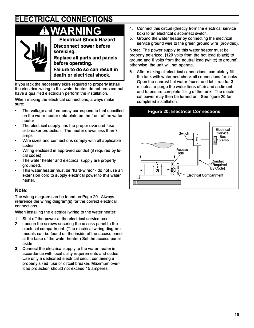
6.After making all electrical connections, completely fill the tank with water and check all connections for leaks. Open the nearest hot water faucet and let it run for 3 minutes to purge the water lines of air and sediment and to ensure complete filling of the tank. The electri- cal power may then be turned on. See figure 20 for completed installation.
Figure 20: Electrical Connections
19