GAS SUPPLY AND PIPING
Explosion Hazard
Use a new AGA or CSA approved gas supply line.
Install a
Do not connect a natural gas water heater to a L.P. Gas Supply.
Do not connect an L.P. gas water heater to a Natural Gas Supply.
Failure to follow these instructions can result in death, explosion, or carbon monoxide poisoning.
Gas Requirements
Read the data plate to be sure the water heater is made for the type of gas being used. This information will be found on the data plate located on the front of the water heater. If the information does not agree with the type of gas available, do not install or operate the water heater. Call your dealer.
Note: An odorant may be added by the gas supplier to the gas used by this water heater. This odorant may fade over an extended period of time. Do not depend upon this odorant as an indication of leaking gas.
Gas Piping
The gas piping must be installed according to all local and state codes or in absence of local and state codes with the “National Fuel Gas Code”, ANSI Z223.1 (NFPA
Note: If using a flexible gas connector, make sure its rating tag matches or exceeds the input of the water heater.
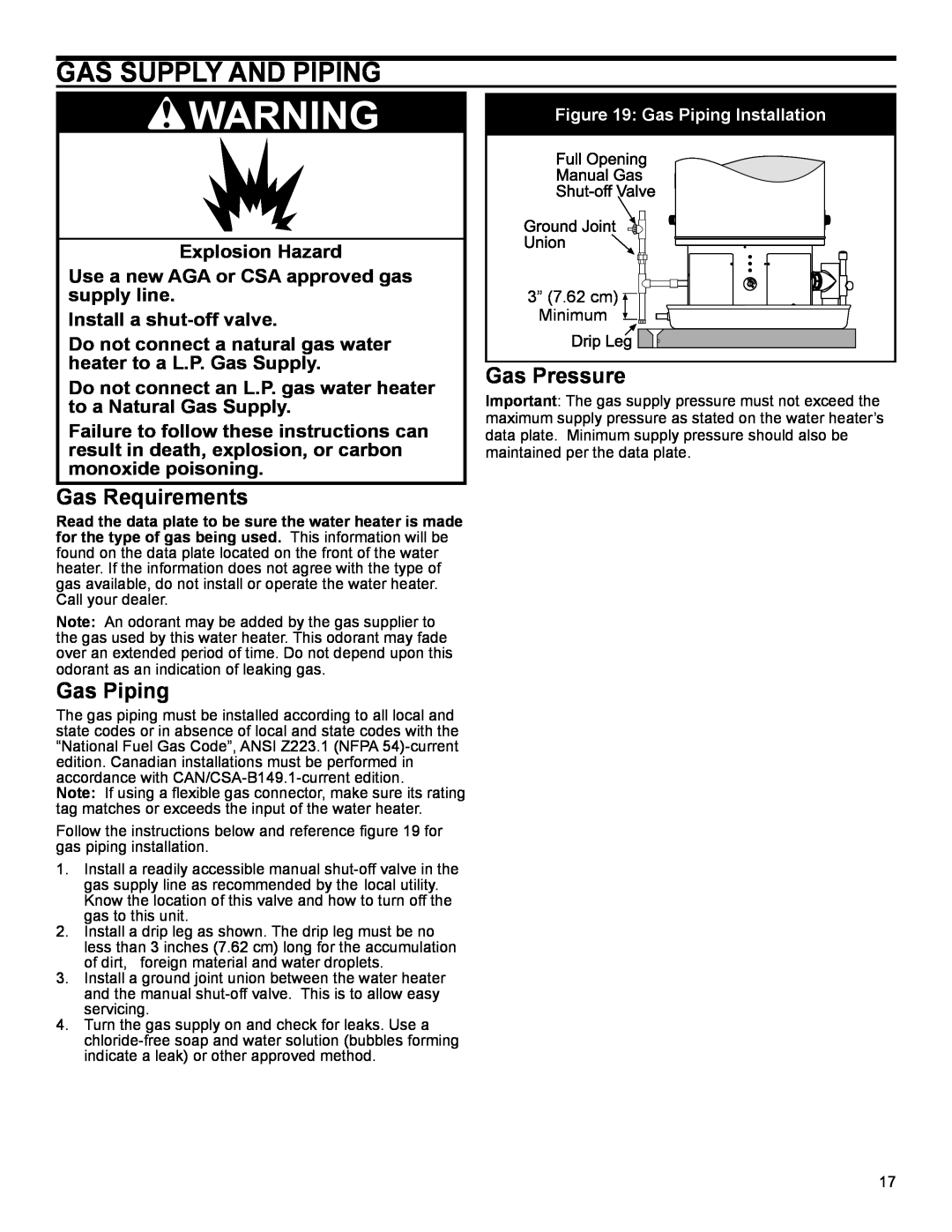
Follow the instructions below and reference figure 19 for gas piping installation.
1.Install a readily accessible manual
2.Install a drip leg as shown. The drip leg must be no less than 3 inches (7.62 cm) long for the accumulation
of dirt, foreign material and water droplets.
3.Install a ground joint union between the water heater and the manual
4.Turn the gas supply on and check for leaks. Use a
Figure 19: Gas Piping Installation
3” (7.62 cm) |
Minimum |
Gas Pressure
Important: The gas supply pressure must not exceed the maximum supply pressure as stated on the water heater’s data plate. Minimum supply pressure should also be maintained per the data plate.
17