Clearances and Accessibility
Notice: Minimum clearances from combustible materi- als are stated on the data plate located on the front of the water heater.
•The water heater is certified for installation on a combustible floor.
Important: If installing over carpeting, the carpeting must be protected by a metal or wood panel beneath the water heater. The protective panel must extend beyond the full width and depth of the water heater by at least 3 inches (7.62 cm) in any direction or if in a alcove or closet instal- lation, the entire floor must be covered by the panel. The panel must be strong enough to carry the weight of the heater when full of water.
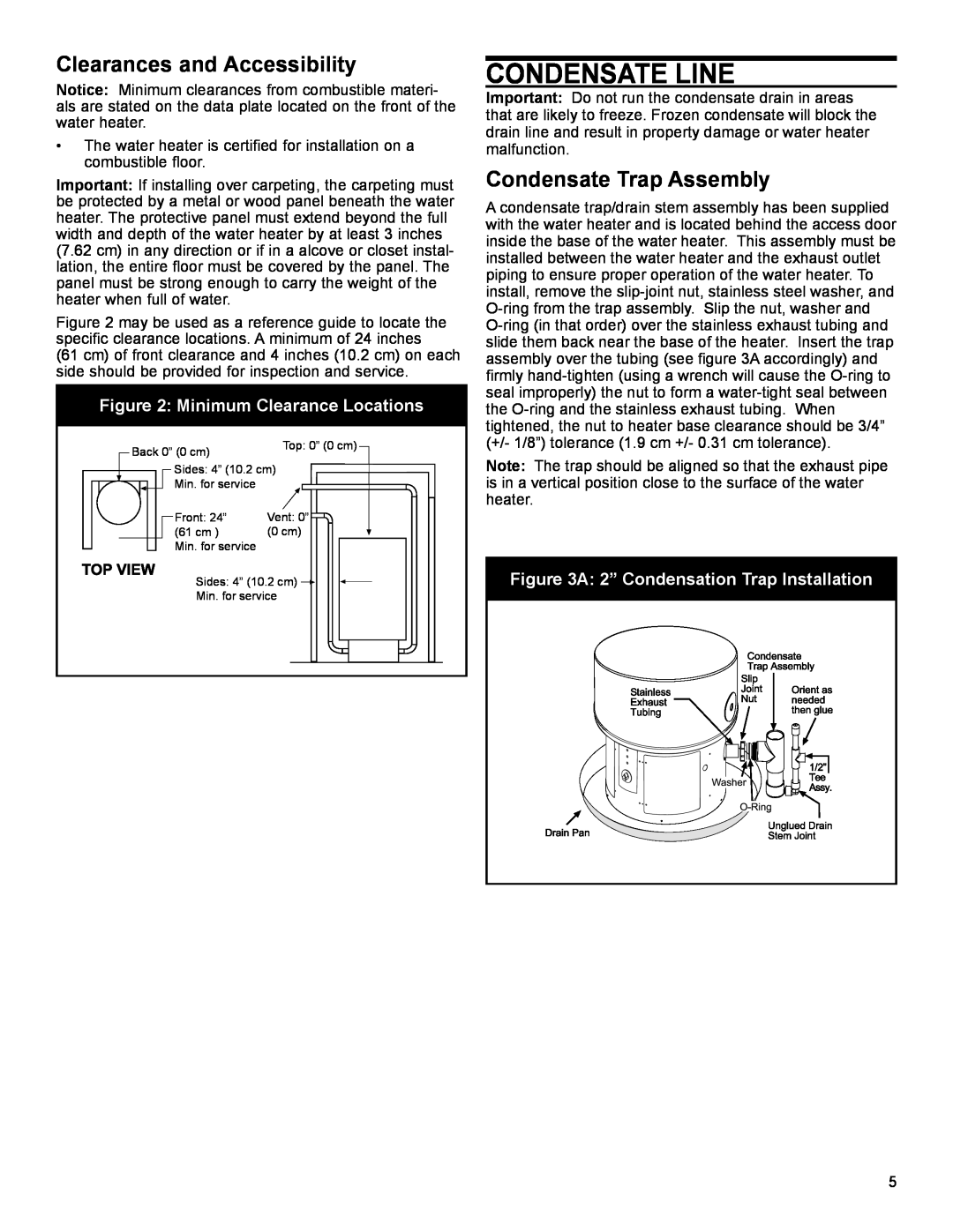
Figure 2 may be used as a reference guide to locate the specific clearance locations. A minimum of 24 inches
(61 cm) of front clearance and 4 inches (10.2 cm) on each side should be provided for inspection and service.
Figure 2: Minimum Clearance Locations
|
|
|
| Back 0” (0 cm) | Top: 0” (0 cm) |
|
| |||||||||||||||||||||
|
|
|
|
|
|
|
|
|
|
|
|
|
|
|
|
|
|
|
|
|
|
| ||||||
|
|
|
|
|
|
|
|
| Sides: 4” (10.2 cm) |
|
|
|
|
|
|
|
|
|
|
|
|
|
|
| ||||
|
|
|
|
|
|
|
|
|
|
|
|
|
|
|
|
|
|
|
|
|
|
|
| |||||
|
|
|
|
|
|
|
|
| Min. for service | Vent: 0” |
|
|
|
|
|
|
|
|
|
|
|
|
|
|
| |||
|
|
|
|
|
|
|
|
| Front: 24” |
|
|
|
|
|
|
|
|
|
|
|
|
|
|
| ||||
|
|
|
|
|
|
|
|
|
|
|
|
|
|
|
|
|
|
|
|
|
|
|
| |||||
|
|
|
|
|
|
|
|
|
|
|
|
|
|
|
|
|
|
|
|
|
|
|
| |||||
|
|
|
|
|
|
|
|
| (61 cm ) | (0 cm) |
|
|
|
|
|
|
|
|
|
|
|
|
|
|
| |||
|
|
|
|
|
|
|
|
|
|
|
|
|
|
|
|
|
|
|
|
|
|
|
| |||||
|
|
|
|
|
|
|
|
| Min. for service |
|
|
|
|
|
|
|
|
|
|
|
|
|
|
|
|
|
|
|
|
|
|
|
|
|
|
|
| Sides: 4” (10.2 cm) |
|
|
|
|
|
|
|
|
|
|
|
|
|
|
|
|
| ||
|
|
|
|
|
|
|
|
|
|
|
|
|
|
|
|
|
|
|
|
|
|
|
|
|
| |||
|
|
|
|
|
|
|
|
|
|
|
|
|
|
|
|
|
|
|
|
|
|
|
| |||||
|
|
|
|
|
|
|
|
|
|
|
|
|
|
|
|
|
|
|
|
|
|
|
|
|
| |||
|
|
|
|
|
|
|
|
| Min. for service |
|
|
|
|
|
|
|
|
|
|
|
|
|
|
| ||||
|
|
|
|
|
|
|
|
|
|
|
|
|
|
|
|
|
|
|
|
|
|
|
|
|
|
|
|
|
|
|
|
|
|
|
|
|
|
|
|
|
|
|
|
|
|
|
|
|
|
|
|
|
|
|
|
|
|
|
|
|
|
|
|
|
|
|
|
|
|
|
|
|
|
|
|
|
|
|
|
|
|
|
|
|
|
|
|
|
|
|
|
|
|
|
|
|
|
|
|
|
|
|
|
|
|
|
|
|
|
|
|
|
|
|
|
CONDENSATE LINE
Important: Do not run the condensate drain in areas that are likely to freeze. Frozen condensate will block the drain line and result in property damage or water heater malfunction.
Condensate Trap Assembly
A condensate trap/drain stem assembly has been supplied with the water heater and is located behind the access door inside the base of the water heater. This assembly must be installed between the water heater and the exhaust outlet piping to ensure proper operation of the water heater. To install, remove the
Note: The trap should be aligned so that the exhaust pipe is in a vertical position close to the surface of the water heater.
Figure 3A: 2” Condensation Trap Installation
5