VERTICAL TERMINATIONS
When 3 inch pipe is used between the water heater and the roof, reduce it to 2 inch pipe before penetrating the roof.
A maximum of 18 inches (45.7 cm) of 2 inch pipe may be used between the 3 inch transition and the inside of the roof.
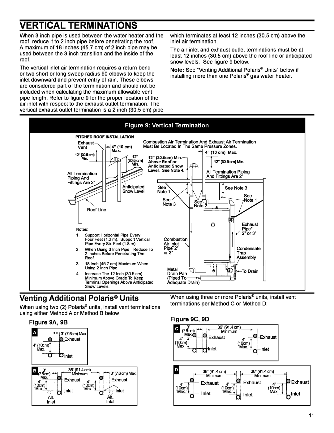
The vertical inlet air termination requires a return bend or two short or long sweep radius 90 elbows to keep the inlet downward and prevent entry of rain. These elbows are considered part of the termination and should not be included when calculating the maximum allowable vent pipe length. Refer to figure 9 for the proper location of the air inlet with respect to the exhaust outlet termination. The vertical exhaust outlet termination is a 2 inch (30.5 cm) pipe
which terminates at least 12 inches (30.5 cm) above the inlet air termination.
The air inlet and exhaust outlet terminations must be at least 12 inches (30.5 cm) above the roof line or anticipated snow levels. See figure 9 below.
Note: See “Venting Additional Polaris® Units” below if installing more than one Polaris® gas water heater.
Figure 9: Vertical Termination
12” (30.5 cm)
Min.
![]()
![]() 4” (10 cm)
4” (10 cm)
Max.
![]() 12” (30.5 cm)
12” (30.5 cm)
Min.
12” (30.5cm) Min. Above Roof or Anticipated Snow ![]()
![]()
![]()
![]() Level. See Note 4.
Level. See Note 4. ![]()
4” (10 cm) Max.
12” (30.5 cm) Min.
Notes:
1. Support Horizontal Pipe Every
Four Feet (1.2 m). Support Vertical
Pipe Every Six Feet (1.8 m).
2. When Using 3 Inch Pipe, Reduce To | * |
2 Inches Before Penetrating The |
|
Roof. |
|
3. 18 Inch (45.7 cm) Maximum When Using 2 Inch Pipe.
4. Increase The 12 Inch (30.5 cm) Minimum Above Grade To Keep Terminal Openings Above Anticipated Snow Levels.
![]()
![]() *
*
Venting Additional Polaris® Units | When using three or more Polaris® units, install vent | ||||||||||||
When using two (2) Polaris® units, install vent terminations | terminations per Method C or Method D: | ||||||||||||
|
|
|
|
|
|
|
| ||||||
using either Method A or Method B below: | Figure 9C, 9D |
|
| ||||||||||
Figure 9A, 9B |
|
| |||||||||||
|
|
|
|
|
|
|
| ||||||
|
|
|
|
|
|
|
|
| 3” | 36” (91.4 cm) |
| ||
|
|
|
| 3” (7.6cm) Max. |
|
|
| (7.6cm) |
|
| Minimum | ||
|
|
|
|
|
|
| Max. |
|
| ||||
| 4” | 4” |
4” (10cm) | (10cm) | (10cm) |
Max. | Max. | |
Max. |
|
|
3” | 36” (91.4 cm) | 3” (7.6 cm) Max. |
(7.6cm) | Minimum | |
Max. |
|
|
4” | 4” |
|
(10cm) | (10cm) |
|
Max. | Max. |
|
4” ![]() (10cm) Max.
(10cm) Max. ![]()
36” (91.4 cm) Minimum ![]()
4” ![]() (10cm) Max.
(10cm) Max. ![]()
36” (91.4 cm) Minimum ![]()
4” ![]()
![]()
![]()
![]()
![]() (10cm)
(10cm)
Max.
11