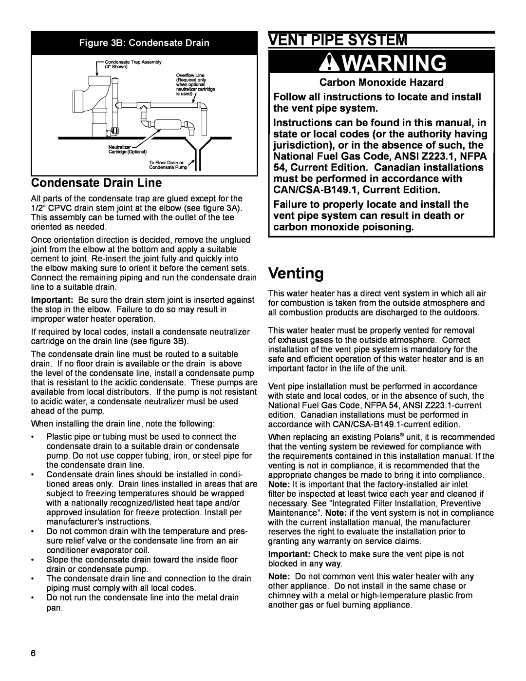
Figure 3B: Condensate Drain
Condensate Drain Line |
All parts of the condensate trap are glued except for the 1/2” CPVC drain stem joint at the elbow (see figure 3A). This assembly can be turned with the outlet of the tee oriented as needed.
Once orientation direction is decided, remove the unglued joint from the elbow at the bottom and apply a suitable cement to joint.
Important: Be sure the drain stem joint is inserted against the stop in the elbow. Failure to do so may result in improper water heater operation.
If required by local codes, install a condensate neutralizer cartridge on the drain line (see figure 3B).
The condensate drain line must be routed to a suitable drain. If no floor drain is available or the drain is above the level of the condensate line, install a condensate pump that is resistant to the acidic condensate. These pumps are available from local distributors. If the pump is not resistant to acidic water, a condensate neutralizer must be used ahead of the pump.
When installing the drain line, note the following:
•Plastic pipe or tubing must be used to connect the condensate drain to a suitable drain or condensate pump. Do not use copper tubing, iron, or steel pipe for the condensate drain line.
•Condensate drain lines should be installed in condi- tioned areas only. Drain lines installed in areas that are subject to freezing temperatures should be wrapped with a nationally recognized/listed heat tape and/or approved insulation for freeze protection. Install per manufacturer’s instructions.
•Do not common drain with the temperature and pres- sure relief valve or the condensate line from an air conditioner evaporator coil.
•Slope the condensate drain toward the inside floor drain or condensate pump.
•The condensate drain line and connection to the drain piping must comply with all local codes.
•Do not run the condensate line into the metal drain pan.
VENT PIPE SYSTEM
Carbon Monoxide Hazard
Follow all instructions to locate and install the vent pipe system.
Instructions can be found in this manual, in state or local codes (or the authority having jurisdiction), or in the absence of such, the National Fuel Gas Code, ANSI Z223.1, NFPA 54, Current Edition. Canadian installations must be performed in accordance with
Failure to properly locate and install the vent pipe system can result in death or carbon monoxide poisoning.
Venting
This water heater has a direct vent system in which all air for combustion is taken from the outside atmosphere and all combustion products are discharged to the outdoors.
This water heater must be properly vented for removal of exhaust gases to the outside atmosphere. Correct installation of the vent pipe system is mandatory for the safe and efficient operation of this water heater and is an important factor in the life of the unit.
Vent pipe installation must be performed in accordance with state and local codes, or in the absence of such, the National Fuel Gas Code, NFPA 54, ANSI
When replacing an existing Polaris® unit, it is recommended that the venting system be reviewed for compliance with the requirements contained in this installation manual. If the venting is not in compliance, it is recommended that the appropriate changes be made to bring it into compliance. Note: It is important that the
filter be inspected at least twice each year and cleaned if necessary. See “Integrated Filter Installation, Preventive Maintenance”. Note: if the vent system is not in compliance with the current installation manual, the manufacturer reserves the right to evaluate the installation prior to granting any warranty on service claims.
Important: Check to make sure the vent pipe is not blocked in any way.
Note: Do not common vent this water heater with any other appliance. Do not install in the same chase or chimney with a metal or
6