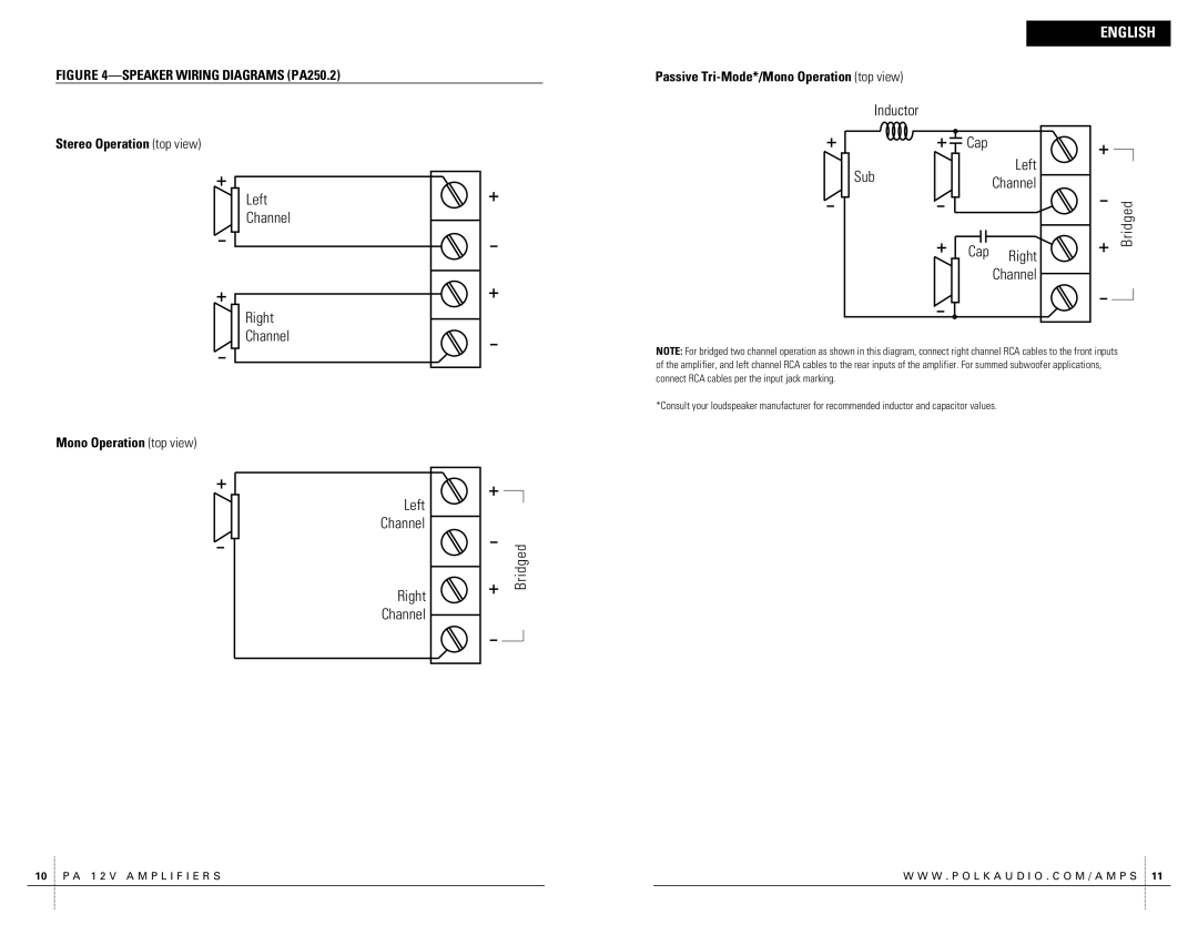
FIGURE 4—SPEAKER WIRING DIAGRAMS (PA250.2)
Stereo Operation (top view)
Left
L C H
Channel
Right
R C H
Channel
Mono Operation (top view)
Left
L C H
Channel
Right
ChannelRH
B r Bridgedi d g e d
ENGLISH
Passive Tri-Mode*/Mono Operation (top view)
Inductor |
|
|
I N D U C T O R |
|
|
| CapA P |
|
| Left |
|
SubU B | L C H | d |
Channel | ||
|
| dig e |
| CapA P Right | Bridged |
| r | |
| ChannelRH | B |
|
|
NOTE: For bridged two channel operation as shown in this diagram, connect right channel RCA cables to the front inputs of the amplifier, and left channel RCA cables to the rear inputs of the amplifier. For summed subwoofer applications, connect RCA cables per the input jack marking.
*Consult your loudspeaker manufacturer for recommended inductor and capacitor values.
10 P A 1 2 V A M P L I F I E R S |
| W W W . P O L K A U D I O . C O M / A M P S 11 |