wire used. IASCA and other auto sound competition organizations have charts available for this; you can also find a chart in the MECP study guide. Minimum wire gauge recommendations for the individual ampli- fiers are listed on the specification page. Always use the same gauge wire for the amplifier ground that you use for the power wire. Be sure to examine the battery ground cable of the vehicle, and if necessary, upgrade it by adding an additional ground wire that is the same gauge as the amplifier’s power wire. Remember, the amplifier can only deliver its rated output when it is not
is generated. For
10. Battery and ground connections to the vehicle should |
be made with crimped ring terminals of the appropriate |
size (surface area is what counts;) soldering the termi- |
nals after crimping is also recommended. |
11. Due to the |
supply, filtering the power cable is not generally required |
(remember that the amp can’t deliver full output if the |
ENGLISH
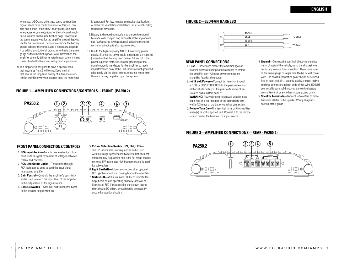
FIGURE 2—LED/FAN HARNESS
| BLACK |
| - |
| BLUE |
| TO LEDs |
|
|
| + |
| BLACK |
| - |
| RED |
| TO FAN |
|
|
| + |
|
|
current limited by the power and ground supply wires.
9.This amplifier is designed to drive a speaker load that measures from 2 to 8 ohms. Keep in mind
that heat is the
power supply is restricted.) Proper grounding of the |
signal source is mandatory for the amplifier to reach |
its performance peak. If the RCA inputs are not grounded |
adequately via the signal source, electrical noise from |
the vehicle may be picked up in the system. |
REAR PANEL CONNECTIONS
1. |
internal electrical damage and are meant to protect |
the amplifier only. All other power connections |
should be fused at the source. |
2. (+) 12 Volt |
a FUSE or CIRCUIT BREAKER to the positive terminal |
of the vehicle battery or the positive terminal of an |
4. |
metal chassis of the vehicle, using the shortest wire |
necessary to make this connection. Always use wire |
of the same gauge or larger than the (+) 12 volt power |
wire. The chassis connection point should be scraped |
free of paint and dirt. Use only quality crimped and/or |
soldered connectors at both ends of this wire. DO NOT |
connect this terminal directly to the vehicle battery |
FIGURE 1—AMPLIFIER CONNECTIONS/CONTROLS—FRONT (PA250.2)
isolated audio system battery. |
WARNING: Always protect this power wire by install- |
ing a fuse or circuit breaker of the appropriate size |
within 12 inches of the battery terminal connection. |
3. Remote Turn |
when (+) 12 volt is applied to it. Connect it to the remote |
turn on lead of the head unit or signal source. |
ground terminal or any other factory ground points. |
5. Speaker |
terminals. (Refer to the Speaker Wiring Diagrams |
section of this guide.) |
FRONT PANEL CONNECTIONS/CONTROLS | 5. |
FIGURE 3—AMPLIFIER CONNECTIONS—REAR (PA250.2)
1.RCA Input
2.RCA Line Output
3.Gain
4.Bass EQ
The HPF attenuates low frequencies and is used with
6.Light
7.Status
8 P A 1 2 V A M P L I F I E R S |
| W W W . P O L K A U D I O . C O M / A M P S 9 |