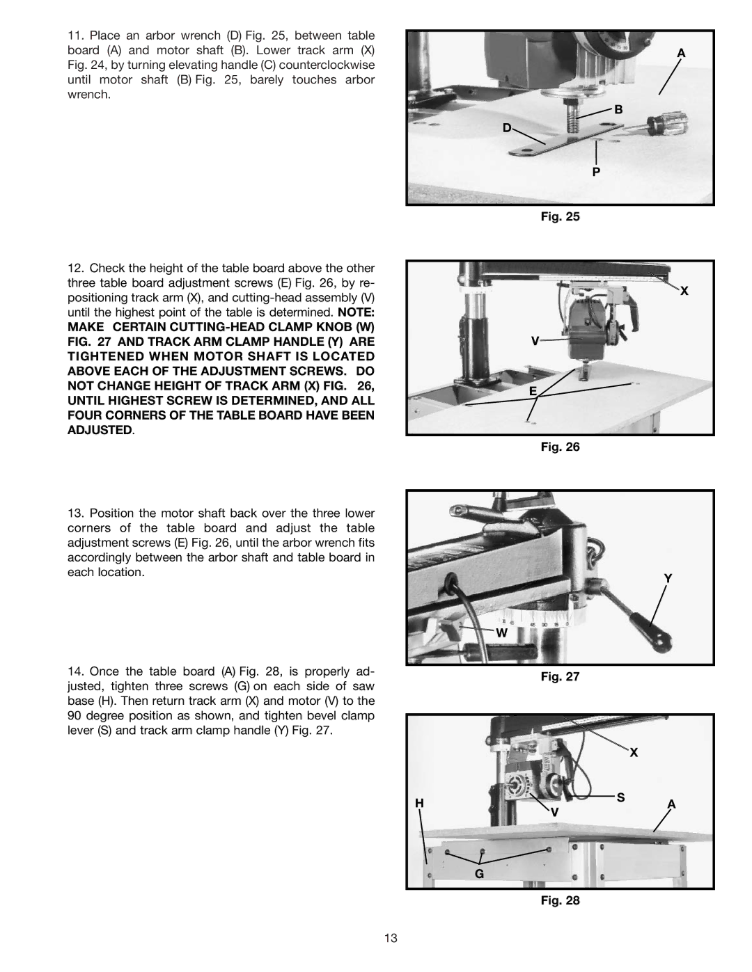
11.Place an arbor wrench (D) Fig. 25, between table board (A) and motor shaft (B). Lower track arm (X) Fig. 24, by turning elevating handle (C) counterclockwise until motor shaft (B) Fig. 25, barely touches arbor wrench.
A
![]() B
B
D
P
Fig. 25
12.Check the height of the table board above the other three table board adjustment screws (E) Fig. 26, by re- positioning track arm (X), and
MAKE CERTAIN
13.Position the motor shaft back over the three lower corners of the table board and adjust the table adjustment screws (E) Fig. 26, until the arbor wrench fits accordingly between the arbor shaft and table board in each location.
14.Once the table board (A) Fig. 28, is properly ad- justed, tighten three screws (G) on each side of saw base (H). Then return track arm (X) and motor (V) to the
90degree position as shown, and tighten bevel clamp lever (S) and track arm clamp handle (Y) Fig. 27.
X
V![]()
E
Fig. 26
Y
![]() W
W
Fig. 27
X
HS A V
G
Fig. 28
13