TABLE BOARD CLAMPS AND TABLE BOARDS
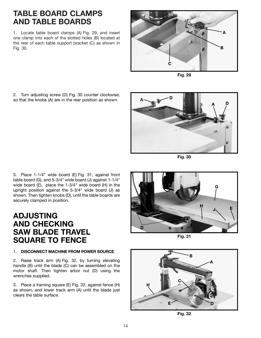
1.Locate table board clamps (A) Fig. 29, and insert one clamp into each of the slotted holes (B) located at the rear of each table support bracket (C) as shown in Fig. 30.
2.Turn adjusting screw (D) Fig. 30 counter clockwise, so that the knobs (A) are in the rear position as shown.
A
B
C
Fig. 29
A![]() D
D
A D
3.Place
ADJUSTING
AND CHECKING
SAW BLADE TRAVEL
SQUARE TO FENCE
1. DISCONNECT MACHINE FROM POWER SOURCE. |
Fig. 30
H
D
Fig. 31
B
G
J E
2. | Raise track arm (A) Fig. 32, by turning elevating |
handle (B) until the blade (C) can be assembled on the | |
motor shaft. Then tighten arbor nut (D) using the | |
wrenches supplied. | |
3. | Place a framing square (E) Fig. 32, against fence (H) |
as shown, and lower track arm (A) until the blade just | |
clears the table surface. | |
![]() A
A
C
H
ED
Fig. 32
14