Grounding Instructions
![]() This machine must be grounded while in use to protect the user from shock
This machine must be grounded while in use to protect the user from shock
In the event of a malfunction or breakdown, grounding provides a path of least resistance for electric current to reduce the risk of electric shock.
If you are not sure whether your outlet is properly grounded, consult a qualified electrician.
Referring to Figure 9: As received from the factory, your mortiser is ready to run at
Operating Controls
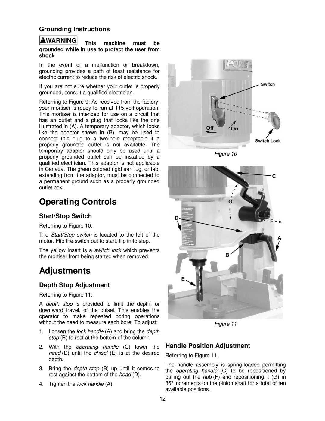
Start/Stop Switch
Referring to Figure 10:
The Start/Stop switch is located to the left of the motor. Flip the switch out to start; flip in to stop.
The yellow insert is a switch lock which prevents the mortiser from being started when removed.
Adjustments
Depth Stop Adjustment
Referring to Figure 11:
A depth stop is provided to limit the depth, or downward travel, of the chisel. This enables the operator to make repeated boring operations without the need to measure each bore. To adjust:
1.Loosen the lock handle (A) and bring the depth stop (B) to rest at the bottom of the column.
2.With the operating handle (C) lower the head (D) until the chisel (E) is at the desired depth.
3.Bring the depth stop (B) up until it comes to rest against the bottom of the head (D).
4.Tighten the lock handle (A).
Figure 10
Figure 11
Handle Position Adjustment
Referring to Figure 11:
The handle assembly is
12