tensioning adjustment, and to set the roller back to the original height.
3.The spring which is located above the bushing block (see Figure 15) must not be compressed too tightly, as this will restrict movement of the infeed roller and may cause machine damage due to flexing of the roller. Lift up the infeed roller with your hand – there should still be sufficient travel in the infeed roller.
4.If necessary, continue to adjust tension and height in combination with one another, while being careful to prevent excess spring compression.
5.Repeat for the other end of the infeed roller. The tension should be equal at both ends of the roller.
Chipbreaker
The functions of the chipbreaker are to break chips into small pieces, help avoid splintering of the wood, help avoid board bounce on thinner boards, and to direct the flow of chips out of the machine.
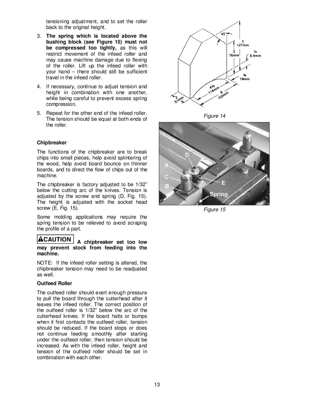
The chipbreaker is factory adjusted to be 1/32” below the cutting arc of the knives. Tension is adjusted by the screw and spring (D, Fig. 15). The height is adjusted with the socket head screw (E, Fig. 15).
Some molding applications may require the spring tension to be relieved to avoid scraping the profile of a part.
![]() A chipbreaker set too low may prevent stock from feeding into the machine.
A chipbreaker set too low may prevent stock from feeding into the machine.
NOTE: If the infeed roller setting is altered, the chipbreaker tension may need to be readjusted as well.
Outfeed Roller
The outfeed roller should exert enough pressure to pull the board through the cutterhead after it leaves the infeed roller. The correct position of the outfeed roller is 1/32” below the arc of the cutterhead knives. If the board halts or bumps when it first contacts the outfeed roller, tension should be reduced. If the board stops or does not continue feeding smoothly after starting under the outfeed roller, then tension should be increased. As with the infeed roller, height and tension of the outfeed roller should be set in combination with each other.
Figure 14
Figure 15
13