5.0Features and Terminology
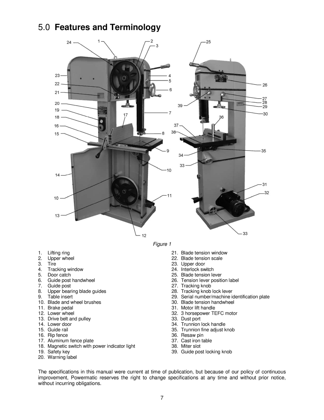
Figure 1
1. | Lifting ring | 21. | Blade tension window |
2. | Upper wheel | 22. | Blade tension scale |
3. | Tire | 23. | Upper door |
4. | Tracking window | 24. | Interlock switch |
5. | Door catch | 25. | Blade tension lever |
6. | Guide post handwheel | 26. | Tension lever position label |
7. | Guide post | 27. | Tracking knob |
8. | Upper bearing blade guides | 28. | Tracking knob lock lever |
9. | Table insert | 29. | Serial number/machine identification plate |
10. | Blade and wheel brushes | 30. | Blade tension handwheel |
11. | Brake pedal | 31. | Motor lift handle |
12. | Lower wheel | 32. | 3 horsepower TEFC motor |
13. | Drive belt and pulley | 33. | Dust port |
14. | Lower door | 34. | Trunnion lock handle |
15. | Guide rail | 35. | Trunnion fine adjust knob |
16. | Rip fence | 36. | Resaw pin |
17. | Aluminum fence plate | 37. | Cast iron table |
18. | Magnetic switch with power indicator light | 38. | Miter slot |
19. | Safety key | 39. | Guide post locking knob |
20. | Warning label |
|
|
The specifications in this manual were current at time of publication, but because of our policy of continuous improvement, Powermatic reserves the right to change specifications at any time and without prior notice, without incurring obligations.
7