V I I . O P E R A T I O N
DX CONTROLLER
The Dynamic DX electronic control system is a modular system. The electronics necessary to operate the power chair are contained in several modules located on different parts of your power chair.
The Dynamic DX system consists of the following components:
νmaster remote (Europa)
νcommunications cable(s)
νpower module
ν | motor wiring harnesses | 1 |
ν | battery wiring harnesses |
|
νactuator lighting module (for optional systems)
The master remote is located typically on the end of an armrest.
The other components are located inside the power base.
2
Europa Master Remote
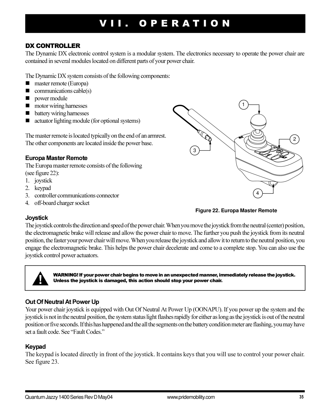
The Europa master remote consists of the following (see figure 22):
1.joystick
2.keypad
3.controller communications connector
4.
3
4
Figure 22. Europa Master Remote
Joystick
The joystick controls the direction and speed of the power chair.When you move the joystick from the neutral (center) position, the electromagnetic brake will release and allow the power chair to move. The further you push the joystick from its neutral position, the faster your power chair will move. When you release the joystick and allow it to return to the neutral position, you engage the electromagnetic brake. This helps the power chair decelerate and come to a complete stop. You can also use the joystick control power actuators.
WARNING! If your power chair begins to move in an unexpected manner, immediately release the joystick. Unless the joystick is damaged, this action should stop your power chair.
Out Of Neutral At Power Up
Your power chair joystick is equipped with Out Of Neutral At Power Up (OONAPU). If you power up the system and the joystick is not in the neutral position, the system status light flashes rapidly for either as long as the joystick is out of the neutral position or five seconds. If this has happened and the all the segments on the battery condition meter are flashing, you may have set a fault code. See “Fault Codes.”
Keypad
The keypad is located directly in front of the joystick. It contains keys that you will use to control your power chair. See figure 23.
Quantum Jazzy 1400 Series Rev D May04 | www.pridemobility.com | 35 |
