Configuration and Data Connectivity
Switch Position(s) | Function | ||
| SW1 | IrDA Interface | |
| OFF | Disabled | |
| ON | Enabled | |
| SW2 | ||
| OFF | Enabled | |
| ON | Disabled | |
| SW3 | ||
| OFF | Disabled | |
| ON | Enabled | |
SW4 |
| SW5 | Baud Rate |
OFF |
| OFF | 38,400 |
OFF |
| ON | 19,200 |
ON |
| OFF | 9,600 |
ON |
| ON | 2,400 |
SW6 |
| SW7 | Parity |
OFF |
| X | No Parity |
ON |
| OFF | Even Parity |
ON |
| ON | Odd Parity |
| SW8 | Reserved | |
Note: Be careful when changing switch settings. Carefully use a pointer on the lever of the switch you wish to change. DO NOT use a lead pencil as this may contaminate the switch. DO NOT use a screw driver or apply excessive force.
Serial RS232C Communication
The RS232C Interface signals for the
Six connections are provided from the Serial Interface to the host computer. The table below lists the Serial Interface signals and pin outs on the RJ connector. A drawing showing the connector pin locations is also provided.
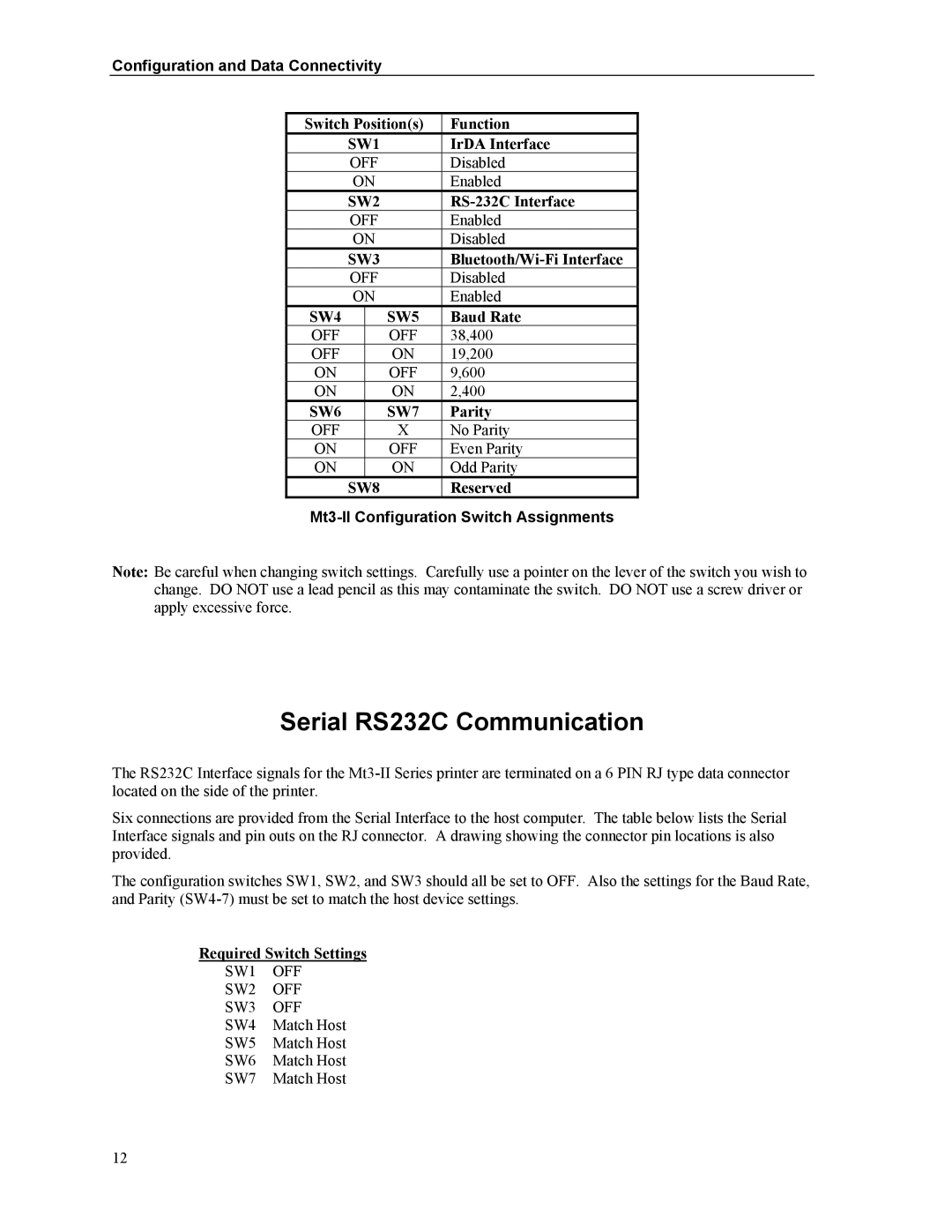
The configuration switches SW1, SW2, and SW3 should all be set to OFF. Also the settings for the Baud Rate, and Parity
Required Switch Settings
SW1 | OFF |
SW2 | OFF |
SW3 | OFF |
SW4 | Match Host |
SW5 | Match Host |
SW6 | Match Host |
SW7 | Match Host |
12
