Programmer’s Reference Manual
Page
Ansi Printers
Copyright 1998, 2002 Printronix, Inc
Trademark Acknowledgements
Trademark Acknowledgements
Table of Contents
Table of Contents
Vertical Page Formatting
Conversion Tables Glossary
Table of Contents
Software Features
About This Manual
Related Product Information
Audience
Installing Printer Emulations
Installing Printer Emulations
Debug
Downloading Software Through the Serial or Parallel Port
Downloading Software Through the Serial or Parallel Port
Navigating to the Appropriate Emulation File on the CD
This is the file you will download into the printer
Cd \downloadEnter
Downloading Software Through Network Interface Card NIC
Downloading Software Through the Network Interface Card NIC
This is the file you will download into the NIC
Downloading Optional Font Files to Flash Memory
Put filename.prgEnter
Downloading Optional Font Files to Flash Memory
Copy /b filename.dwn LPT2Enter
Copy /b filename1.dwn+filename2.dwn+...LPT1Enter
Message Explanation Required Action
Flash Memory Message Guide
Flash Memory Message Guide
Error Program not
Error Security PAL
Error Short AT
Error Writing to
Flash Memory Message Guide Explanation Required Action
Installing Printer Emulations
Ansi Emulation Default Settings
Overview
CR = CR
CPI
LPI
CPI
Control Codes
Configuring The Ansi Emulation
Configuring The Ansi Emulation
DC3 Device Control-3 13H
Control Codes
Format For Control Code Descriptions
Escape Control Codes Overview
Format For Control Code Descriptions
Control Codes Index
Graphics Commands
Vertical Formatting Commands
Character Sets, International
Character Sets, International
Ascii Code ESC p1 Hex Code 1B 5B p1 Dec Code 27 91 p1
Ansi International Character Sets
ISO Italian
Ascii Code ESC p1p2 SP B
Expanded Mode
Expanded Mode
Forms Length, Top Margin, Bottom Margin
Ascii Code ESC p1p2p3 r
Graphic Rendition
Graphic Rendition
Ascii Code ESC p1p2...pn m
Character Types and Enhancements Parameter
Line Spacing
Ascii Code ESC p1p2 s
Margins, Left and Right
Margins, Left and Right
Proportional Print Mode
Private Mode, Disable
Private Mode, Enable
Resetting
Resetting
Hardcoded Reset Values
Ascii Code ESC c Hex Code Dec Code
Tab, Clear
Subscript
Superscript
Tab Set, Multiple Horizontal
Vertical Position Relative
Terminate Loading of Data
Vertical Position Absolute
Graphics
Dot Patterns And Densities
Dot Patterns And Densities
0X0X0X0 LSB LSB Msbx MSB
Graphics Ascii Character Dot Patterns Hex Dots
654321
Horizontal Format
Vertical Format
Horizontal Format Ascii Character Dot Patterns Hex Dots
Horizontal Format Byte → Byte n Row ↓
Repeat Graphics Character
Other Graphics Considerations
Dot Graphics
Select Graphics Mode
Setting Bar Code Parameters
Default Bar Code Parameters
Bar Codes
Entering And Exiting Bar Codes
Setting Bar Code Parameters
P1 Values
If p1 = Style
UPC a
Bar Codes P1 Values
Postnet
P9 Values
Rotation/Font
Human Readable Line HRL
Spacing Between Bar Codes
Bar Code Readers
Bar Code Readers
Test Program
Vertical Bar Codes
Vertical Bar Codes
Oversize Character Font Option
Oversize Character Font Option
Entering And Exiting Oversize
Selecting Size
Selecting Size
Oversize Character Font Option
Vertical Page Formatting
Planning a Vertical Page Format
VFU Characteristics
Proprinter And Epson Vertical Tab Table
Executing Vertical Tabs
Vertical Tab Positions
Vertical Tab Positions
Form Data Form Line Number Vertical Tabs
Series Evfu
Start Load Code 1E or 6E Hex
Channel Assignment
End Load 1F or 6F Hex
Using The Evfu
Using The Evfu
Series Evfu Codes PI Line Enabled
Data Bits Hex Dec Code Channel
Series Evfu Series Evfu Codes PI Line Enabled
Series Evfu Codes PI Line Disabled or Not Used
DLE
DC1 DC2 DC3 DC4 NAK SYN ETB Can SUB ESC
Data Bits Hex Dec Code Channel End Load
Clearing The Evfu Memory
Relative Line Slewing
DLE DC1 DC2 DC3 DC4 NAK SYN ETB Can SUB ESC
Ansi Evfu Series Evfu Line Slewing
Data Bits Lines Hex Dec Code
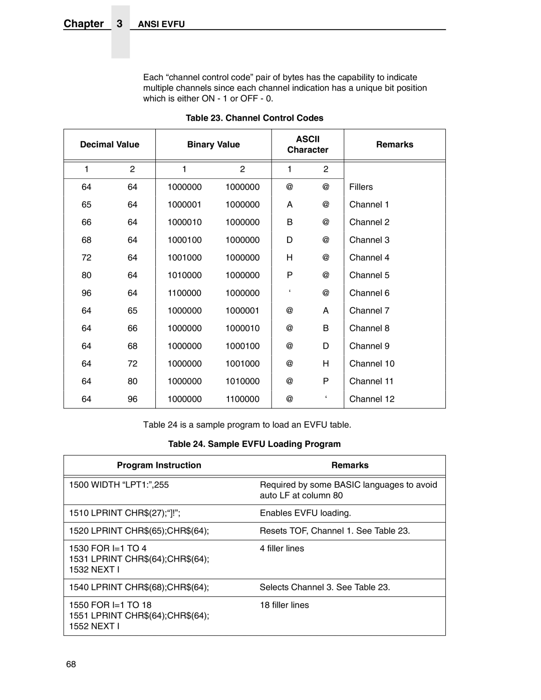
Loading the Table
Loading the Table
Ascii Code ESC Hex Code 1B 5D Dec Code 27 93
Two Byte Channel Control Code Format
Ansi Evfu
Channel Control Codes Decimal Value Binary Value
Remarks
Character
Description
Default
Default Evfu Table
Skip to Channel Command
Ansi Evfu Default Evfu Table Channel Description
Skip To Channel Example Program Instruction Remarks Output
Downloading The Evfu Using The PI Line
Downloading The Evfu Using The PI Line
Ansi Evfu Two Byte Channel Control Code Format
Skip to Channel Command
Ansi Evfu
Standard Ascii Character Set
Appendix a
Equivalent Columns Conversion Table Inches
13.3 16.7
Appendix B
Decipoints for Column vs. CPI Values
Margin CPI Column
111
Margin CPI Column
Appendix B
Margin Column CPI
Appendix B
Acia
Ascii
Character weight, as shown in this sentence
For example Bold refers to a heavy or thick
CTA
CPU
CT+
CTS
Cvfu
Davfu
DCD
DSR
DTR
Dvfu
Ebcdic
Fifo
IGP
HGS
Ieee
LAC
LCD
LED
MPL
Nack
NLQ
Nvfu
Nvram
PAL
PCB
Pcba
PGL
POR
PSA
RAM
ROM
SCS
RTS
SAA
Sfcc
SLD
SNA
SOH
TOF
TTL
UPC
Uset
OFF
100
Diagnostics Passed
Ansi
Error Occurred / Flushing QUEUES*, 20 ESC Sequence
Security Code Violation
Please WAIT... Reset in Progress
Loading Program from Port XX%
104
Page
164305-001D