Frame Assembly
1.Before beginning, make sure that you have read and understood the information on page 4.
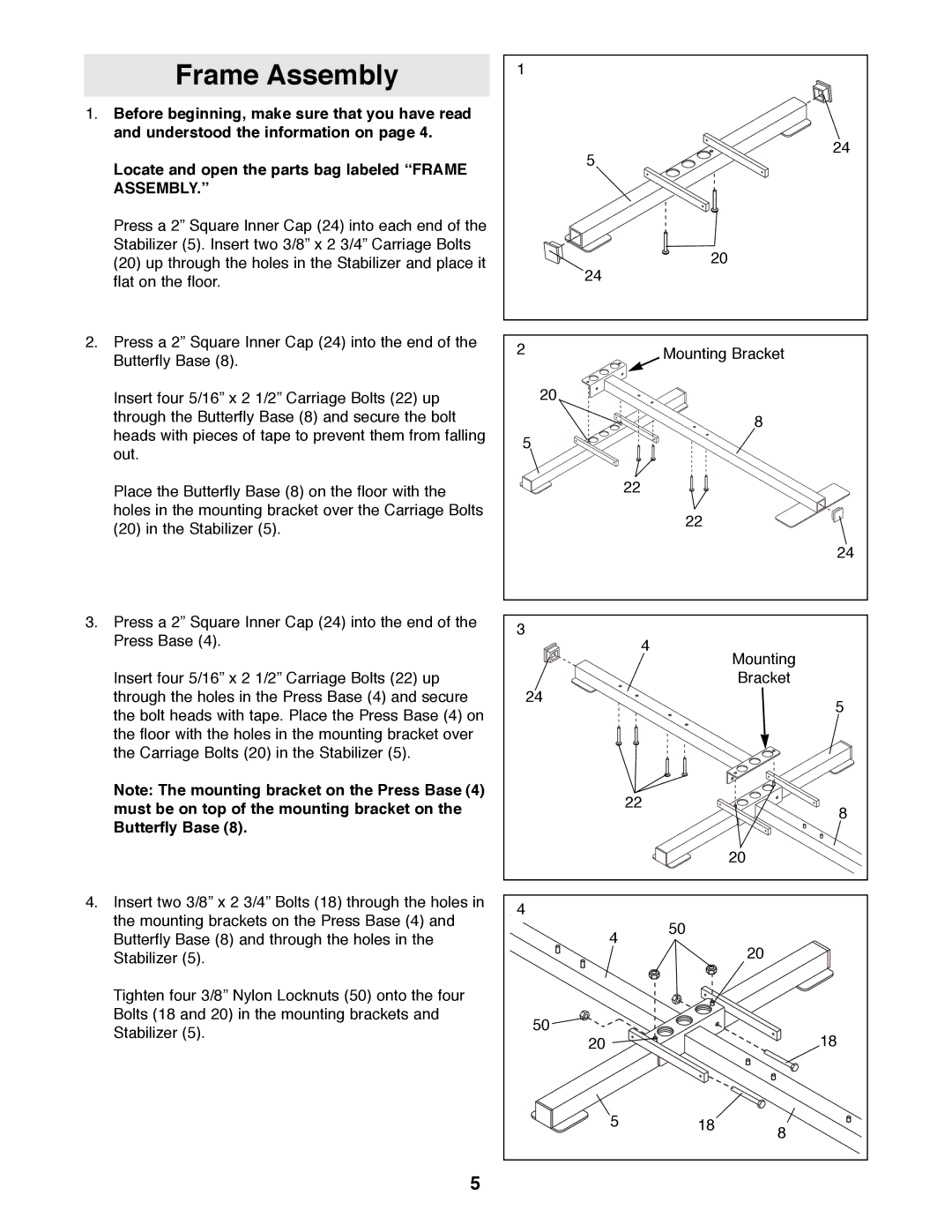
Locate and open the parts bag labeled ÒFRAME ASSEMBLY.Ó
Press a 2Ó Square Inner Cap (24) into each end of the Stabilizer (5). Insert two 3/8Ó x 2 3/4Ó Carriage Bolts
(20)up through the holes in the Stabilizer and place it flat on the floor.
2.Press a 2Ó Square Inner Cap (24) into the end of the Butterfly Base (8).
Insert four 5/16Ó x 2 1/2Ó Carriage Bolts (22) up through the Butterfly Base (8) and secure the bolt heads with pieces of tape to prevent them from falling out.
Place the Butterfly Base (8) on the floor with the holes in the mounting bracket over the Carriage Bolts
(20)in the Stabilizer (5).
3.Press a 2Ó Square Inner Cap (24) into the end of the Press Base (4).
Insert four 5/16Ó x 2 1/2Ó Carriage Bolts (22) up through the holes in the Press Base (4) and secure the bolt heads with tape. Place the Press Base (4) on the floor with the holes in the mounting bracket over the Carriage Bolts (20) in the Stabilizer (5).
Note: The mounting bracket on the Press Base (4) must be on top of the mounting bracket on the Butterfly Base (8).
4.Insert two 3/8Ó x 2 3/4Ó Bolts (18) through the holes in the mounting brackets on the Press Base (4) and Butterfly Base (8) and through the holes in the Stabilizer (5).
Tighten four 3/8Ó Nylon Locknuts (50) onto the four Bolts (18 and 20) in the mounting brackets and Stabilizer (5).
1 |
|
| 24 |
| 5 |
| 20 |
| 24 |
2 | Mounting Bracket |
|
20 |
|
|
|
| 8 |
5 |
|
|
| 22 |
|
| 22 |
|
|
| 24 |
3 | 4 |
|
| Mounting | |
|
| |
|
| Bracket |
24 |
| 5 |
|
| |
| 22 | 8 |
|
| |
|
| 20 |
4 |
|
|
4 | 50 |
|
| 20 | |
|
| |
50 |
| 18 |
20 |
| |
5 | 18 | 8 |
|
|
5