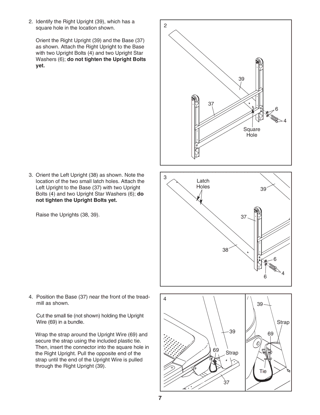
2. Identify the Right Upright (39), which has a | 2 |
|
|
|
square hole in the location shown. |
|
|
| |
|
|
|
| |
Orient the Right Upright (39) and the Base (37) |
|
|
|
|
as shown. Attach the Right Upright to the Base |
|
|
|
|
with two Upright Bolts (4) and two Upright Star |
|
|
|
|
Washers (6); do not tighten the Upright Bolts |
|
|
|
|
yet. |
|
|
|
|
|
|
| 39 |
|
| 37 |
|
| 6 |
|
|
|
| |
|
|
|
| 4 |
|
|
| Square |
|
|
|
| Hole |
|
3. Orient the Left Upright (38) as shown. Note the | 3 |
|
|
|
location of the two small latch holes. Attach the |
|
|
| |
Latch |
|
|
| |
Left Upright to the Base (37) with two Upright | Holes |
| 39 |
|
Bolts (4) and two Upright Star Washers (6); do |
|
|
| |
|
|
|
| |
not tighten the Upright Bolts yet. |
|
|
|
|
Raise the Uprights (38, 39). |
|
| 37 |
|
|
|
|
| |
|
| 38 |
|
|
|
|
|
| 6 |
|
|
| 6 | 4 |
|
|
|
| |
4. Position the Base (37) near the front of the tread- | 4 |
|
|
|
mill as shown. |
| 39 |
| |
|
|
| ||
Cut the small tie (not shown) holding the Upright |
|
|
|
|
Wire (69) in a bundle. |
|
|
| Strap |
Wrap the strap around the Upright Wire (69) and |
| 39 |
| 69 |
|
|
| ||
secure the strap using the included plastic tie. |
|
|
|
|
Then, insert the connector into the square hole in | 69 | Strap |
|
|
the Right Upright. Pull the opposite end of the |
|
| ||
|
|
| ||
strap until the end of the Upright Wire is pulled |
|
|
|
|
through the Right Upright (39). |
|
| Tie |
|
|
|
|
| |
|
| 37 |
|
|
| 7 |
|
|
|