ASSEMBLY
To hire an authorized service technician to assemble the treadmill, call
Assembly requires the included hex keys | and your own phillips screwdriver | , rubber | |
mallet | , adjustable wrench | , and needlenose pliers | . |
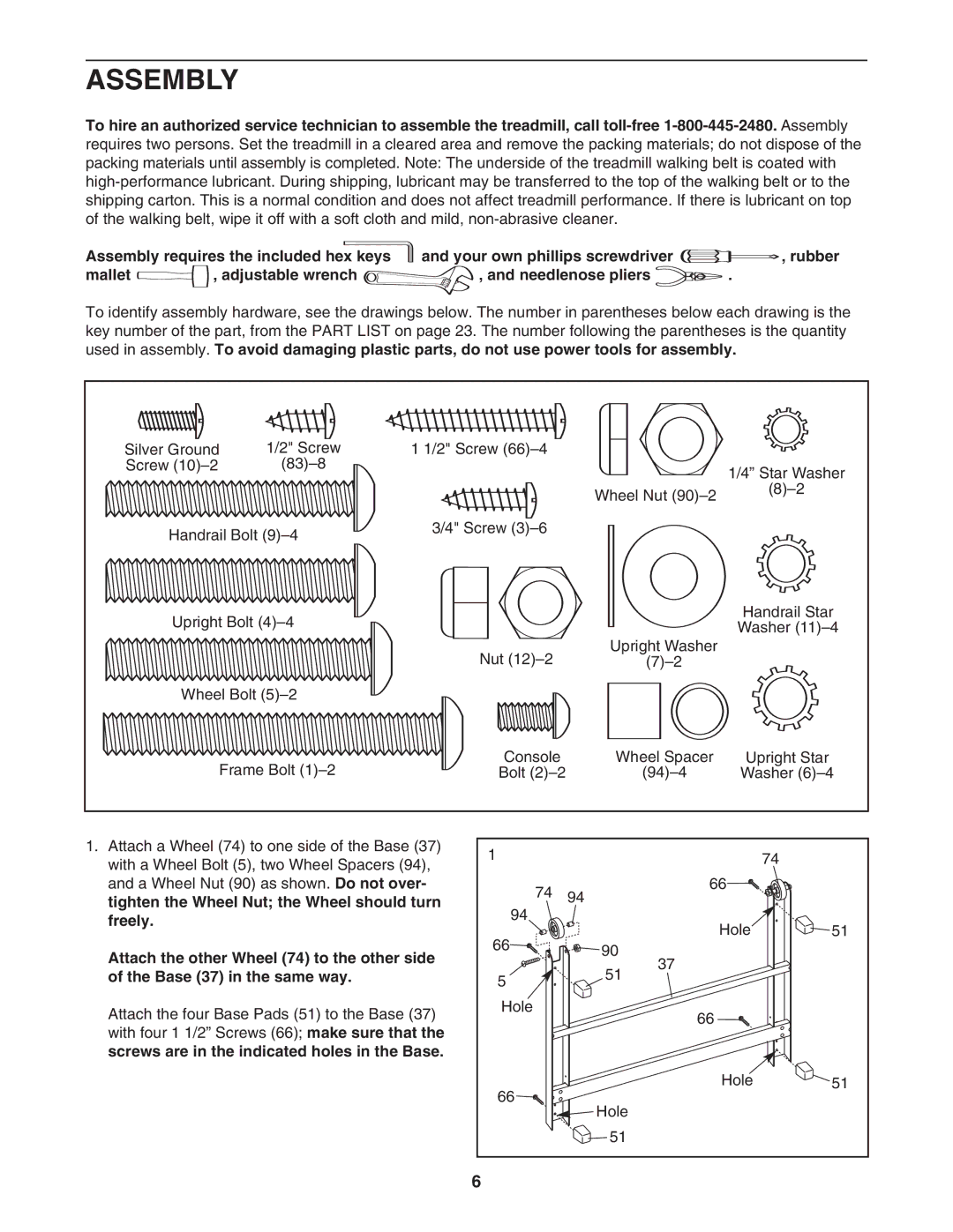
To identify assembly hardware, see the drawings below. The number in parentheses below each drawing is the key number of the part, from the PART LIST on page 23. The number following the parentheses is the quantity used in assembly. To avoid damaging plastic parts, do not use power tools for assembly.
Silver Ground | 1/2" Screw | 1 1/2" Screw |
|
|
Screw |
|
| 1/4” Star Washer | |
|
|
|
| |
|
|
| Wheel Nut | |
|
|
|
| |
Handrail Bolt | 3/4" Screw |
|
| |
|
|
| ||
Upright Bolt |
|
| Handrail Star | |
|
| Washer | ||
|
|
|
| |
|
| Nut | Upright Washer |
|
|
|
| ||
Wheel Bolt |
|
|
| |
Frame Bolt | Console | Wheel Spacer | Upright Star | |
Bolt | Washer | |||
1.Attach a Wheel (74) to one side of the Base (37) with a Wheel Bolt (5), two Wheel Spacers (94), and a Wheel Nut (90) as shown. Do not over- tighten the Wheel Nut; the Wheel should turn freely.
Attach the other Wheel (74) to the other side of the Base (37) in the same way.
Attach the four Base Pads (51) to the Base (37) with four 1 1/2” Screws (66); make sure that the screws are in the indicated holes in the Base.
1 |
| 74 | |
74 | 66 |
| |
94 |
| ||
94 | Hole | 51 | |
66 | |||
90 |
| ||
|
| ||
| 37 |
| |
5 | 51 |
| |
|
| ||
Hole | 66 |
| |
|
| ||
66 | Hole | 51 | |
Hole |
| ||
|
| ||
| 51 |
| |
6 |
|
|