R
Castile Pellet Stove
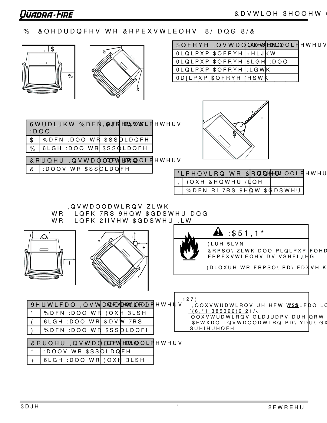
B. Clearances to Combustibles (UL and ULC)
A |
B |
C |
C |
Alcove Installation | Inches | Millimeters |
Minimum Alcove Height | 43 | 1092 |
Minimum Alcove Side Wall | 6 | 152 |
Minimum Alcove Width | 38 | 965 |
Maximum Alcove Depth | 36 | 914 |
Straight Back Against | Inches | Millimeters | ||
Wall |
|
|
| |
A |
| Back Wall to Appliance | 2 | 51 |
B |
| Side Wall to Appliance | 6 | 152 |
|
|
| ||
Corner Installation | Inches | Millimeters | ||
C |
| Walls to Appliance | 2 | 51 |
I |
J |
C |
L |
Dimension to Corner | Inches | Millimeters | |
I | Flue Center Line | 264 | |
J | Back of Top Vent Adapter | 232 | |
Installations with:
3 to 3 inch Top Vent Adapter and
3 to 6 inch Offset Adapter Kit
F | D | G | H |
|
| H | |
|
|
| |
| E |
|
|
|
|
| G |
Vertical Installation | Inches | Millimeters | |
D | Back Wall to Flue Pipe | 3 | 76 |
E | Side Wall to Cast Top | 6 | 152 |
F | Back Wall to Appliance | 8 | 203 |
Corner Installation | Inches | Millimeters | |
G | Walls to Appliance | 2 | 51 |
H | Side Wall to Flue Pipe | 3 | 76 |
![]() WARNING
WARNING
Fire Risk.
Comply with all minimum clearances to combustibles as specified.
Failure to comply may cause house fire.
NOTE:
•Illustrations reflect typical installations and are FOR DESIGN PURPOSES ONLY.
•Illustrations/diagrams are not drawn to scale.
•Actual installation may vary due to individual design preference.
Page 8 | October 11, 2005 |
