Power-up Modes
Enable Status Display
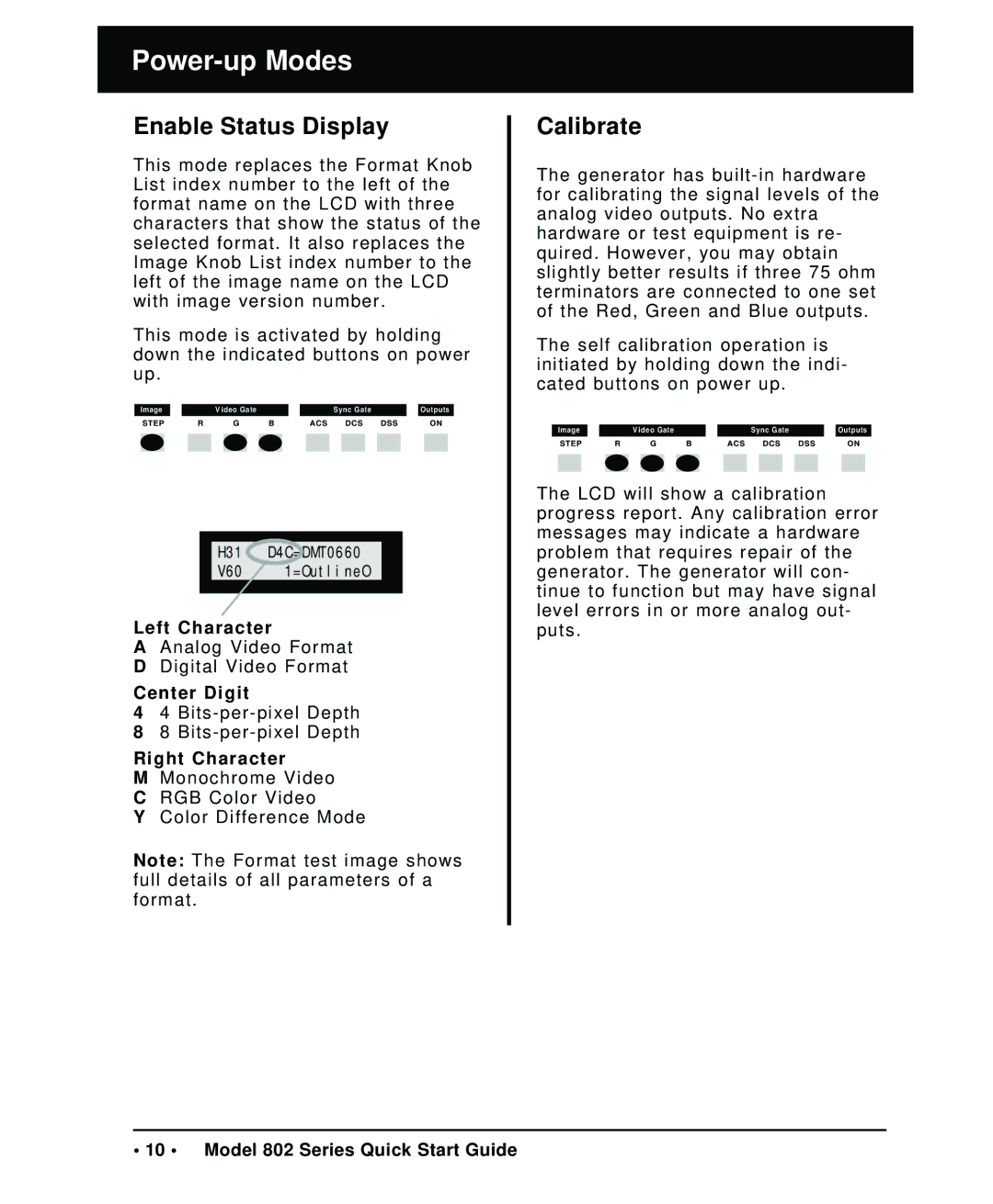
This mode replaces the Format Knob List index number to the left of the format name on the LCD with three characters that show the status of the selected format. It also replaces the Image Knob List index number to the left of the image name on the LCD with image version number.
This mode is activated by holding down the indicated buttons on power up.
| Image |
|
| Video Gate |
|
|
| Sync Gate |
|
| Outputs | |||||||
| STEP | R |
| G | B |
| ACS |
| DCS | DSS |
|
| ON | |||||
|
|
|
|
|
|
|
|
|
|
|
|
|
|
|
|
|
|
|
|
|
|
|
|
|
|
|
|
|
|
|
|
|
|
|
|
|
|
H31 D4C=DMT0660
V60 1=OutlineO
Left Character
AAnalog Video Format D Digital Video Format
Center Digit
44
88
Right Character
MMonochrome Video C RGB Color Video
Y Color Difference Mode
Note: The Format test image shows full details of all parameters of a format.
Calibrate
The generator has
The self calibration operation is initiated by holding down the indi- cated buttons on power up.
Image |
|
|
| V ideo Gate |
|
|
|
|
| Sync Gate |
|
|
| Outputs | ||||||||
| STEP | R |
| G | B |
|
|
| ACS |
| DCS | DSS |
|
|
| ON | ||||||
|
|
|
|
|
|
|
|
|
|
|
|
|
|
|
|
|
|
|
|
|
|
|
|
|
|
|
|
|
|
|
|
|
|
|
|
|
|
|
|
|
|
|
|
|
|
The LCD will show a calibration progress report. Any calibration error messages may indicate a hardware problem that requires repair of the generator. The generator will con- tinue to function but may have signal level errors in or more analog out- puts.
• 10 • Model 802 Series Quick Start Guide
