Making Connections
VGA Connector Pinout Chart
High Density 15
Pin # | Signal | Pin# | Signal | Pin # | Signal |
1 | Analog Red Video | 6 | Analog Video Ground | 11 | No Connection |
2 | Analog Green Video | 7 | Analog Video Ground | 12 | DDC/EDID Serial Data |
3 | Analog Blue Video | 8 | Analog Video Ground | 13 | Horizontal Sync |
4 | No Connection | 9 | DDC/EDID +5 VDC Out | 14 | Vertical Sync |
5 | Digital Ground | 10 | Digital Ground | 15 | DDC/EDID Data Clock |
DVI Connector Pinout Chart (DVI Options Only)
Pin# | Signal | Pin# | Signal | Pin# | Signal | Pin# | Signal |
|
|
|
|
|
|
|
|
1 | TMDS D2- | 9 | TMDS D1- | 17 | TMDS D0- | C1 | Analog Red |
|
|
|
|
|
|
|
|
2 | TMDS D2+ | 10 | TMDS D1+ | 18 | TMDS D0+ | C2 | Analog Green |
|
|
|
|
|
|
|
|
3 | D2/4 Shield | 11 | D1/3 Shield | 19 | D0/5 Shield | C3 | Analog Blue |
|
|
|
|
|
|
|
|
4 | TMDS D4- | 12 | TMDS D3- | 20 | TMDS D5- | C4 | Horiz Sync |
|
|
|
|
|
|
|
|
5 | TMDS D4+ | 13 | TMDS D3+ | 21 | TMDS D5+ | C5 | Analog Ground |
6 | DDC Clock | 14 | +5 V DC | 22 | Clock Shield |
|
|
|
|
|
|
|
|
|
|
7 | DDC Data | 15 | Ground | 23 | TMDS Clock+ |
|
|
|
|
|
|
|
|
|
|
8 | No Conn. | 16 | Hot Plug Detect | 24 | TMDS Clock- |
|
|
|
|
|
|
|
|
|
|
LVDS Connector Pinout Chart (LVDS Option Only)
Pin# | Signal | Pin# | Signal | Pin# | Signal | Pin# | Signal |
1 | A0M | 10 | DDC Clock | 19 | A0P | 28 | DDC Data |
|
|
|
|
|
|
|
|
2 | A1M | 11 | DDC +5VDC | 20 | A1P | 29 | USB Ground |
3 | A2M | 12 | USB+ | 21 | A2P | 30 | USB- |
4 | Clock 1M | 13 | USB +5VDC | 22 | Clock 1P | 31 | Shield Ground |
5 | A3M | 14 | A4M | 23 | A3P | 32 | A4P |
|
|
|
|
|
|
|
|
6 | Shield | 15 | A5M | 24 | No Conn | 33 | A5P |
7 | No Conn | 16 | A6M | 25 | No Conn | 34 | A6P |
8 | No Conn | 17 | A7M | 26 | No Conn | 35 | A7P |
9 | No Conn | 18 | Clock 2M | 27 | DDC Ground | 36 | Clock 2P |
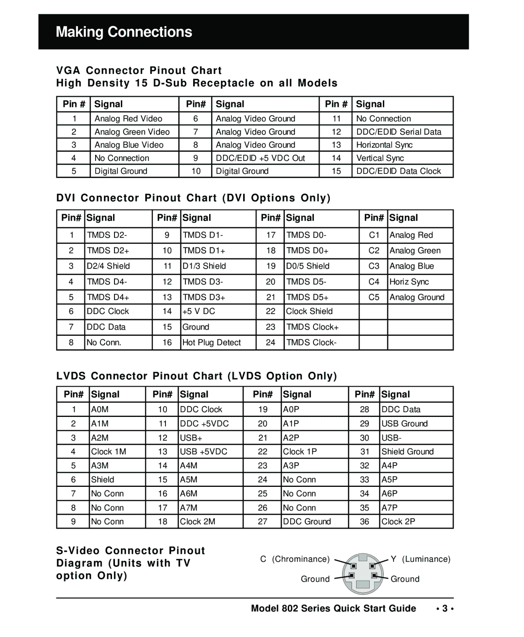
S-Video Connector Pinout Diagram (Units with TV option Only)
C(Chrominance) Ground
Y(Luminance) Ground
Model 802 Series Quick Start Guide | • 3 • |