Front Panel Controls and Indicators (Normal Mode)
LCD Window Information
Vertical Rate | Horizontal Rate | Current | Current |
nearest Hz | nearest KHz | Format | Test Image |
Power On Indicator |
|
|
|
802
Video
Test
Generator
H31 219=VGA_3
V60 198=SMPTE133
Format |
Image |
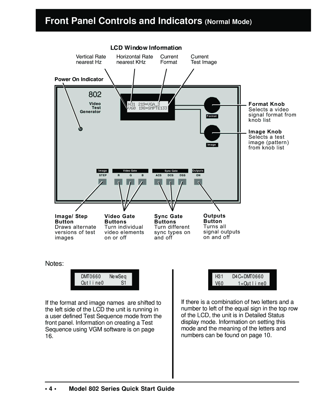
Format Knob Selects a video signal format from knob list
Image Knob Selects a test image (pattern) from knob list
| Image |
|
| Video Gate |
|
|
| Sync Gate |
|
| Outputs | |||||||
| STEP | R |
| G | B |
| ACS |
| DCS | DSS |
|
| ON | |||||
|
|
|
|
|
|
|
|
|
|
|
|
|
|
|
|
|
|
|
|
|
|
|
|
|
|
|
|
|
|
|
|
|
|
|
|
|
|
Image/ Step | Video Gate | Sync Gate |
Button | Buttons | Buttons |
Draws alternate | Turn individual | Turn different |
versions of test | video elements | sync types on |
images | on or off | and off |
Outputs
Button Turns all signal outputs on and off
Notes:
DMT0660 NewSeq
Outline0 S1
If the format and image names are shifted to the left side of the LCD the unit is running in a user defined Test Sequence mode from the front panel. Information on creating a Test Sequence using VGM software is on page 16.
H31 D4C=DMT0660
V60 1=Outline0
If there is a combination of two letters and a number to left of the equal sign in the top row of the LCD, the unit is in Detailed Status display mode. Information on setting this mode and the meaning of the letters and numbers can be found on page 10.
• 4 • Model 802 Series Quick Start Guide
