MODEM CONTROL REGISTER
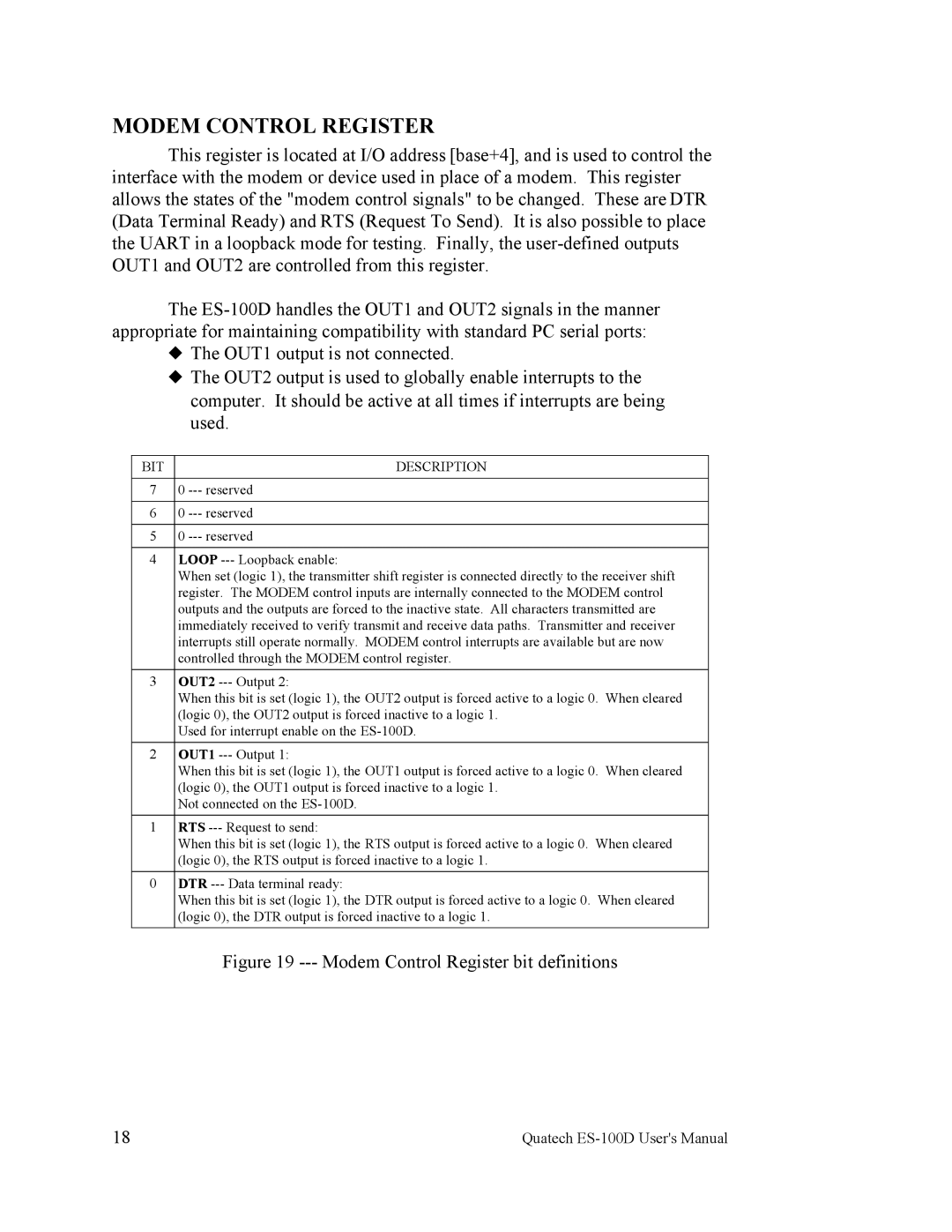
This register is located at I/O address [base+4], and is used to control the interface with the modem or device used in place of a modem. This register allows the states of the "modem control signals" to be changed. These are DTR (Data Terminal Ready) and RTS (Request To Send). It is also possible to place the UART in a loopback mode for testing. Finally, the
The
| The OUT1 output is not connected. | |
| The OUT2 output is used to globally enable interrupts to the | |
|
| computer. It should be active at all times if interrupts are being |
|
| used. |
|
|
|
BIT |
| DESCRIPTION |
|
|
|
7 |
| 0 |
|
|
|
6 |
| 0 |
|
|
|
5 |
| 0 |
|
|
|
4 |
| LOOP |
|
| When set (logic 1), the transmitter shift register is connected directly to the receiver shift |
|
| register. The MODEM control inputs are internally connected to the MODEM control |
|
| outputs and the outputs are forced to the inactive state. All characters transmitted are |
|
| immediately received to verify transmit and receive data paths. Transmitter and receiver |
|
| interrupts still operate normally. MODEM control interrupts are available but are now |
|
| controlled through the MODEM control register. |
3 |
| OUT2 |
|
| When this bit is set (logic 1), the OUT2 output is forced active to a logic 0. When cleared |
|
| (logic 0), the OUT2 output is forced inactive to a logic 1. |
|
| Used for interrupt enable on the |
2 |
| OUT1 |
|
| When this bit is set (logic 1), the OUT1 output is forced active to a logic 0. When cleared |
|
| (logic 0), the OUT1 output is forced inactive to a logic 1. |
|
| Not connected on the |
1 |
| RTS |
|
| When this bit is set (logic 1), the RTS output is forced active to a logic 0. When cleared |
|
| (logic 0), the RTS output is forced inactive to a logic 1. |
0 |
| DTR |
|
| When this bit is set (logic 1), the DTR output is forced active to a logic 0. When cleared |
|
| (logic 0), the DTR output is forced inactive to a logic 1. |
|
| Figure 19 |
18 | Quatech |