Fit the Handles
Remove the 4mm Allen screws from the doors with the hexagon key tool. Use the screws to fit the door handles.
The handles should be above the fixings.
Remove the 4mm Allen screws from the top corners of the fascia and fix the front handrail in position.
Fitting the splash back (optional)
Remove the two fixing screws (3mm hexagonal socket head) and nuts that pass through the top of the rear flue grille. Hold the splash back in position. From the rear refit the 2 fixing screws and nuts.
Fitting a stability bracket
A stability bracket or chain (not supplied by with the cooker) should be fitted when the cooker is connected to a flexible gas supply.
When fitting a stability bracket read these instructions together with the leaflet supplied with the bracket.
1.Place the cooker in its intended position and level the cooker.
2.Draw a pencil line 70mm from the front edge of the levelling feet.
3.Mark the centre line for the bracket by measuring 550mm from the left hand side of the cooker.
4.Lower the front roller and move the cooker forward.
5.Measure back from the pencil line 550mm to locate the front edge of the bracket. Fix the bracket to the floor.
6.Measure the height from floor level to engagement edge in back of cooker. Add 3mm to this dimension and assemble the stability bracket to this height. (i.e. from floor level to underside of the top member) and ensure the bracket does not foul the oven burner assembly.
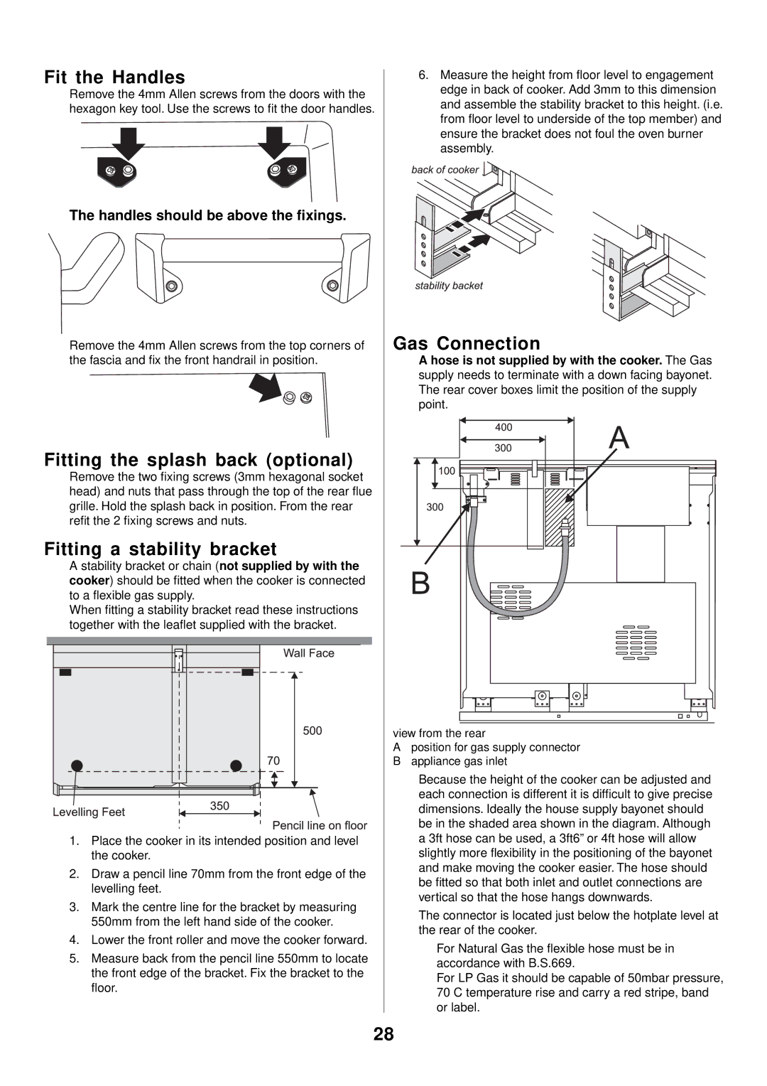
Gas Connection
A hose is not supplied by with the cooker. The Gas supply needs to terminate with a down facing bayonet. The rear cover boxes limit the position of the supply point.
view from the rear
Aposition for gas supply connector
Bappliance gas inlet
Because the height of the cooker can be adjusted and each connection is different it is difficult to give precise dimensions. Ideally the house supply bayonet should be in the shaded area shown in the diagram. Although a 3ft hose can be used, a 3ft6” or 4ft hose will allow slightly more flexibility in the positioning of the bayonet and make moving the cooker easier. The hose should be fitted so that both inlet and outlet connections are vertical so that the hose hangs downwards.
The connector is located just below the hotplate level at the rear of the cooker.
For Natural Gas the flexible hose must be in accordance with B.S.669.
For LP Gas it should be capable of 50mbar pressure, 70 C temperature rise and carry a red stripe, band or label.
28