If in doubt contact, your supplier.
Screw the threaded end of the hose into the gas inlet in the underside of the connector block on the back of the cooker.
After completing the gas connection, check the cooker is gas sound with a pressure test.
Pressure testing
The gas pressure can be measured at one of the LH hotplate burner injectors. Lift off a burner head. Fit the pressure gauge to the injector. Turn on the hotplate burner and turn on and light one of the other hotplate burners.
For Natural Gas cookers the pressure should be 20mbar.
For LP Gas cookers the pressure should be 29mbar for Butane
37mbar for Propane.
Reassemble burner top, making sure it is reassembled in the correct way on the burner body.
Electrical Connection
WARNING: THIS COOKER MUST BE EARTHED.
All external wiring must comply with the IEE Regulations for the Electrical Equipment of Buildings. Connection
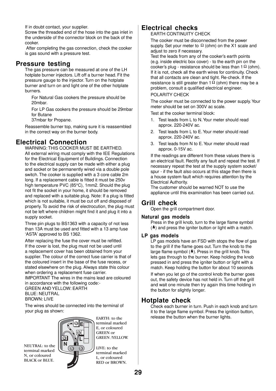
to the electrical supply can be made with either a plug and socket or be permanently wired via a double pole switch. The cooker is supplied with a 3 core cable 2m long. If a replacement cable is fitted it must be 250v high temperature PVC (85°C), 1mm2. Should the plug not fit the socket in your home, it should be removed and replaced with a suitable plug. Note: If a plug is fitted which is not suitable, it must be cut off and disposed of properly. To avoid the risk of electrocution, the plug must not be left where children might find it and plug it into a supply socket.
Three pin plugs to BS1363 with a capacity of not less than 13A must be used and fitted with a 13 amp fuse ‘ASTA’ approved to BS 1362.
After replacing the fuse the cover must be refitted. If the cover is lost, the plug must not be used until a replacement cover has been obtained from your supplier. The colour of the correct fuse carrier is that of the coloured insert in the base of the fuse recess, or stated elsewhere on the plug. Always state this colour when ordering a replacement fuse carrier. IMPORTANT The wires in the mains lead are coloured in accordance with the following code:-
GREEN AND YELLOW: EARTH
BLUE: NEUTRAL
BROWN: LIVE
The wires should be connected into the terminal of your plug as shown:
Electrical checks
EARTH CONTINUITY CHECK
The cooker must be disconnected from the power supply. Set your meter to ![]() (ohm) on the X1 scale and adjust to zero if necessary.
(ohm) on the X1 scale and adjust to zero if necessary.
Test the leads from any of the cooker’s earth points (e.g. inside electric box cover) - to the earth pin on the cooker’s plug - resistance should be less than 1 ![]() (ohm). If it is not, check all the earth wires for continuity. Check that all contacts are clean and tight.
(ohm). If it is not, check all the earth wires for continuity. Check that all contacts are clean and tight. ![]() (ohm) there may be a problem, consult a qualified electrical engineer.
(ohm) there may be a problem, consult a qualified electrical engineer.
POLARITY CHECK
The cooker must be connected to the power supply. Your meter should be set on 300V ac scale.
Test at the cooker terminal block:
1.Test leads from L to N. Your meter should read approx.
2.Test leads from L to E. Your meter should read approx.
3.Test leads from N to E. Your meter should read approx.
If the readings are different from these values there is an electrical fault. Rectify any fault and repeat the test. If necessary repeat the test at the supply system socket/ spur - if the fault also occurs at this stage then there is a house system fault which requires attention by the Electrical Authority.
The customer should be warned NOT to use the appliance until this examination has been carried out.
Grill check
Open the grill compartment door.
Natural gas models
Press in the grill knob, turn to the large flame symbol (![]() ) and press the igniter button or light with a match.
) and press the igniter button or light with a match.
LP gas models
LP gas models have an FSD with stops the flow of gas to the grill if the flame goes out. Turn the knob to the large flame symbol (![]() ). Press in the grill knob. This lets gas through to the burner. Keep holding the knob pressed in and press the igniter button or light with a match. Keep holding the button for about 10 seconds
). Press in the grill knob. This lets gas through to the burner. Keep holding the knob pressed in and press the igniter button or light with a match. Keep holding the button for about 10 seconds
If when you let go of the control knob the burner goes out, the safety device has not held in. Turn off the grill and wait one minute then try again this time holding in the button for slightly longer.
Hotplate check
Check each burner in turn. Push in each knob and turn it to the large flame symbol. Press the ignition button, release the button when the burner lights.
29