WARNING - SERVICING TO BE CARRIED OUT ONLY BY AN AUTHORISED PERSON
Disconnect from electricity and gas before servicing. Check appliance is safe when you have finished.
Servicing Notes | Right hand tray | |||||
From the rear remove the screws securing the | ||||||
| When servicing or replacing gas carrying components | flue grille to the hotplate tray. If the LH hotplate | ||||
| has not been removed, slacken the screws | |||||
| disconnect from gas before commencing operation | |||||
| holding the L H tray. Remove pan support, | |||||
| and check appliance is gas sound after completion. | |||||
| burner head, caps and trim rings. Remove the | |||||
| When checking for gas leaks use a liquid leak detector | |||||
| screws holding the Wok burner to the hotplate. | |||||
| at all joints and connections to check for leaks in the | |||||
| Remove the 4 screws and washers holding | |||||
| system. Use a product specifically manufactured for | |||||
| the RH tray to the frame. Taking care not to | |||||
| leak detection. In GB refer to BS 6891; in IE refer to the | |||||
| damage the Wok burner electrode, lift tray and | |||||
| current edition of IS 813. | |||||
| withdraw. | |||||
| Leak testing of the appliance shall be conducted in | |||||
| Reassemble in reverse order ensuring that the leads are | |||||
| accordance to the manufacturer’s instructions. | |||||
| reconnected. When replacing the RH hotplate take care | |||||
CAUTION: DO NOT USE A FLAME TO CHECK | ||||||
not to damage the ignition electrode of the Wok burner. | ||||||
FOR GAS LEAKS. | It is important that the rear fixing screws are refitted as | |||||
| Do not use | they from part of the cooker earthing. | ||||
| Disconnect from electricity supply before commencing | On some models there is a separate plate. | ||||
| servicing, particularly before removing any of the |
|
|
| ||
|
|
|
| |||
| following: control panel, side panels, cooktop tray, or |
|
|
| ||
| any of the electrical components or cover boxes. Before |
|
|
| ||
|
|
|
| |||
| electrical reconnection check that the appliance is |
|
|
| ||
| electrically safe. |
|
|
| ||
1 To Remove the Control Panel |
|
|
| |||
| Disconnect from electricity supply. |
|
|
|
| |
| Open the oven door & grill door and remove the fixing |
|
|
| ||
| screws underneath the control panel. The screws |
|
|
| ||
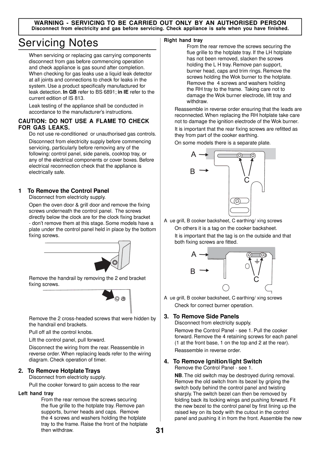
| directly below the clock are for the clock fixing bracket | A fl ue grill, B cooker backsheet, C earthing/fi xing screws | ||||
| - don’t remove them at this stage. Some models have a | |||||
| On others it is a tag on the cooker backsheet. | |||||
| plate under the control panel held in place by the bottom | |||||
| fixing screws. | It is important that the tag is on the outside and that | ||||
|
|
| both fixing screws are fitted. | |||
Remove the handrail by removing the 2 end bracket |
|
|
|
| ||
fixing screws. |
|
|
|
| ||
|
|
|
| A fl ue grill, B cooker backsheet, C earthing/fi xing screws | ||
|
|
|
| Check for correct burner operation. | ||
Remove the 2 | 3. To Remove Side Panels | |||||
| Disconnect from electricity supply. |
| ||||
the handrail end brackets. |
|
|
| |||
| Remove the Control Panel - see 1. Pull the cooker | |||||
Pull off all the control knobs. |
| |||||
| forward. Remove the 4 retaining screws for each panel | |||||
Lift the control panel, pull forward. |
| |||||
| (1 at the front base, 1 on the top and 2 at the rear). | |||||
Disconnect the wiring from the rear. Reassemble in |
| |||||
| Reassemble in reverse order. | |||||
reverse order. When replacing leads refer to the wiring |
| |||||
|
|
|
| |||
diagram. Check operation of timer. |
| 4. To Remove Ignition/light Switch | ||||
2. To Remove Hotplate Trays |
| Remove the Control Panel - see 1. | ||||
| NB. The old switch may be destroyed during removal. | |||||
| Disconnect from electricity supply. |
|
| |||
Pull the cooker forward to gain access to the rear |
| Remove the old switch from its bezel by griping the | ||||
| switch body behind the control panel and twisting | |||||
Left hand tray |
| |||||
| sharply. The switch bezel can then be removed by | |||||
| From the rear remove the screws securing |
| folding back its locking wings and pushing forward. Fit | |||
| the flue grille to the hotplate tray. Remove pan |
| the new bezel to the control panel by first lining up the | |||
| supports, burner heads and caps. Remove |
| raised key on its body with the cutout in the control | |||
| the 4 screws and washers holding the hotplate |
| panel and pushing it in from the front. Assemble the new | |||
| tray to the frame. Raise the front of the hotplate | 31 |
|
| ||
| then withdraw. |
|
| |||