36.Once the pressure switch signal is received at the ignition module the hot surface igniter is energized by a 120 VAC signal from S-1 on the ignition mod- ule. (The hot surface igniter must draw greater than 3.1 amps while being energized or ignition lockout will occur after three tries.)

37.Once the ignition module determines that the hot surface igniter amp draw is within specs and oper- ating properly, a 24 VAC signal is output from pin GV on the module.

38.24 VAC signal is received to gas valve 1 thus ener- gizing it.

39.The stage 1 LED on the diagnostics display board is now illuminated.

40.The coil of relay K-2 (N.O.) is now energized with the (K-2) contacts closing downstream of the stage 2 connections.

41.The gas coming through the burners should ignite from the heat of the hot surface igniter and the flame should carry over from one burner to the other burners of stage 1. The remote sensor is now trying to sense the flame. If the flame is not sensed within 4 seconds, the ignition module will shut down the gas valve and retry the hot surface igniter. During ignition retry the heater must per- form a 15-second pre-purge and an approximate- ly 30-second igniter warm-up before opening gas valve 1 again. The standard ignition module will attempt ignition a maximum of three times prior to ignition lockout.

42.(Models 302A-402A only) 24 VAC is now waiting at pin 3 of the stage 2 connection on the CPW board.

43.(Models 502A-902A only) After gas valve 1 opens and flame rectification is received, time delay relay 1 (TD-1) starts a 5-second countdown.

44.(Models 502A-902A only) After the 5 second countdown from TD-1, 24 VAC is waiting at pin 3 of the stage 2 connection on the CPW board.

45.After closure of the stage 2 contacts Gas valve 2 in energized.

46.The stage 2 LED on the diagnostics display board is now illuminated.

47.The heater is now operating at full fire.

Ignition Module

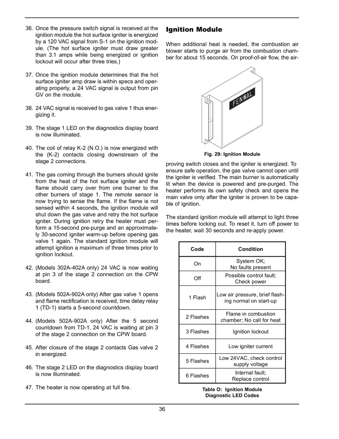
When additional heat is needed, the combustion air blower starts to purge air from the combustion cham- ber for about 15 seconds. On proof-of-air flow, the air-

Fig. 29: Ignition Module

proving switch closes and the igniter is energized. To ensure safe operation, the gas valve cannot open until the igniter is verified. The main burner is automatically lit when the device is powered and pre-purged. The heater performs its own safety check and opens the main valve only after the igniter is proven to be capa- ble of ignition.

The standard ignition module will attempt to light three times before locking out. To reset it, turn off power to the heater, wait 30 seconds and re-apply power.

Code

Condition


On

System OK;

No faults present


Off

Possible control fault;

Check power


1 Flash

Low air pressure, brief flash-

ing normal on start-up


2 Flashes

Flame in combustion

chamber; No call for heat


3 Flashes

Ignition lockout


4 Flashes

Low igniter current


5 Flashes

Low 24VAC, check control

supply voltage


6 Flashes

Internal fault;

Replace control


Table O: Ignition Module

Diagnostic LED Codes

36

Page 36
Image 36
Raypak 302A-902A manual Ignition Module, Code Condition

302A-902A specifications

The Raypak 302A-902A is a highly regarded pool and spa heater, known for its efficiency and reliability in delivering warmth to residential and commercial aquatic applications. This heater stands out due to its robust design, advanced technology, and user-friendly features.

One of the key characteristics of the Raypak 302A-902A is its dual fuel capability, which means it can run on either natural gas or propane. This flexibility allows users to choose their preferred fuel type, contributing to operational efficiency and cost-effectiveness. With a BTU output ranging from 302,000 to 902,000, the Raypak heater is capable of quickly heating large volumes of water, making it ideal for pools, spas, and hot tubs.

The heater incorporates advanced technology such as a stainless steel heat exchanger, which not only ensures excellent thermal conductivity but also promotes durability against corrosion. This is especially advantageous in harsh environments, where exposure to chemicals can significantly impact the lifespan of traditional copper heat exchangers. The Raypak 302A-902A's heat exchanger is designed to withstand the rigors of constant use while maintaining high performance levels.

Another prominent feature of the Raypak 302A-902A is its digital display control system, which simplifies the operation and monitoring of the heater. Users can easily set and adjust temperatures, as well as access diagnostic information, all through an intuitive interface. This digital control not only enhances user experience but also aids in the timely maintenance of the unit.

Energy efficiency is another major selling point of the Raypak 302A-902A. The heater is designed with environmentally friendly practices in mind, utilizing a low NOx burner that minimizes harmful emissions. This not only meets environmental regulations but also makes it a greener alternative for heating needs.

In terms of installation, the compact design of the Raypak 302A-902A allows for versatile placement options, whether in a residential backyard or a commercial environment. Its user-friendly installation process ensures that homeowners and businesses alike can enjoy the benefits of heated water with minimal hassle.

Overall, the Raypak 302A-902A is an exemplary choice for anyone seeking a high-quality, efficient, and flexible pool and spa heating solution. Its combination of robust engineering, advanced technology, and user-focused features solidifies its position as a leader in the market, promising effective heating for years to come. Whether for personal enjoyment or commercial use, this heater delivers exceptional performance that meets diverse heating needs.