WARNING: Vent connectors serving appliances vented by natural draft shall not be connected into any portion of mechanical draft systems operating under a positive pressure.

Horizontal Through-the-Wall Venting (Category IV)

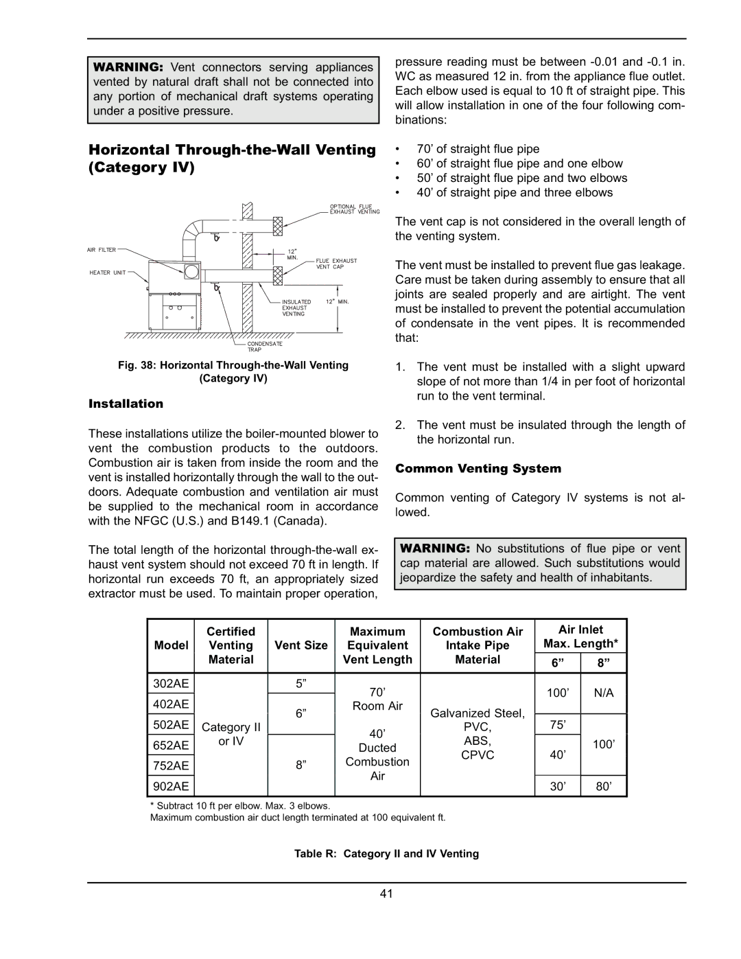
Fig. 38: Horizontal Through-the-Wall Venting

(Category IV)

Installation

These installations utilize the boiler-mounted blower to vent the combustion products to the outdoors. Combustion air is taken from inside the room and the vent is installed horizontally through the wall to the out- doors. Adequate combustion and ventilation air must be supplied to the mechanical room in accordance with the NFGC (U.S.) and B149.1 (Canada).

The total length of the horizontal through-the-wall ex- haust vent system should not exceed 70 ft in length. If horizontal run exceeds 70 ft, an appropriately sized extractor must be used. To maintain proper operation,

pressure reading must be between -0.01 and -0.1 in. WC as measured 12 in. from the appliance flue outlet. Each elbow used is equal to 10 ft of straight pipe. This will allow installation in one of the four following com- binations:

70’ of straight flue pipe

60’ of straight flue pipe and one elbow

50’ of straight flue pipe and two elbows

40’ of straight pipe and three elbows

The vent cap is not considered in the overall length of the venting system.

The vent must be installed to prevent flue gas leakage. Care must be taken during assembly to ensure that all joints are sealed properly and are airtight. The vent must be installed to prevent the potential accumulation of condensate in the vent pipes. It is recommended that:

1.The vent must be installed with a slight upward slope of not more than 1/4 in per foot of horizontal run to the vent terminal.

2.The vent must be insulated through the length of the horizontal run.

Common Venting System

Common venting of Category IV systems is not al- lowed.

WARNING: No substitutions of flue pipe or vent cap material are allowed. Such substitutions would jeopardize the safety and health of inhabitants.


Certified


Maximum

Combustion Air


Air Inlet


Model

Venting

Vent Size

Equivalent

Intake Pipe


Max. Length*


Material


Vent Length

Material


6”

8”


302AE


5”

70’


100’

N/A


402AE


6”

Room Air

Galvanized Steel,


502AE


75’


Category II


40’

PVC,


652AE

or IV


ABS,


100’


Ducted


CPVC


40’


752AE


8”

Combustion


Air


902AE


30’

80’


* Subtract 10 ft per elbow. Max. 3 elbows.

Maximum combustion air duct length terminated at 100 equivalent ft.

Table R: Category II and IV Venting

41

Page 41
Image 41
Raypak 302A-902A manual Certified Maximum Combustion Air Air Inlet Model Venting, Material Vent Length, 100’ Ducted

302A-902A specifications

The Raypak 302A-902A is a highly regarded pool and spa heater, known for its efficiency and reliability in delivering warmth to residential and commercial aquatic applications. This heater stands out due to its robust design, advanced technology, and user-friendly features.

One of the key characteristics of the Raypak 302A-902A is its dual fuel capability, which means it can run on either natural gas or propane. This flexibility allows users to choose their preferred fuel type, contributing to operational efficiency and cost-effectiveness. With a BTU output ranging from 302,000 to 902,000, the Raypak heater is capable of quickly heating large volumes of water, making it ideal for pools, spas, and hot tubs.

The heater incorporates advanced technology such as a stainless steel heat exchanger, which not only ensures excellent thermal conductivity but also promotes durability against corrosion. This is especially advantageous in harsh environments, where exposure to chemicals can significantly impact the lifespan of traditional copper heat exchangers. The Raypak 302A-902A's heat exchanger is designed to withstand the rigors of constant use while maintaining high performance levels.

Another prominent feature of the Raypak 302A-902A is its digital display control system, which simplifies the operation and monitoring of the heater. Users can easily set and adjust temperatures, as well as access diagnostic information, all through an intuitive interface. This digital control not only enhances user experience but also aids in the timely maintenance of the unit.

Energy efficiency is another major selling point of the Raypak 302A-902A. The heater is designed with environmentally friendly practices in mind, utilizing a low NOx burner that minimizes harmful emissions. This not only meets environmental regulations but also makes it a greener alternative for heating needs.

In terms of installation, the compact design of the Raypak 302A-902A allows for versatile placement options, whether in a residential backyard or a commercial environment. Its user-friendly installation process ensures that homeowners and businesses alike can enjoy the benefits of heated water with minimal hassle.

Overall, the Raypak 302A-902A is an exemplary choice for anyone seeking a high-quality, efficient, and flexible pool and spa heating solution. Its combination of robust engineering, advanced technology, and user-focused features solidifies its position as a leader in the market, promising effective heating for years to come. Whether for personal enjoyment or commercial use, this heater delivers exceptional performance that meets diverse heating needs.