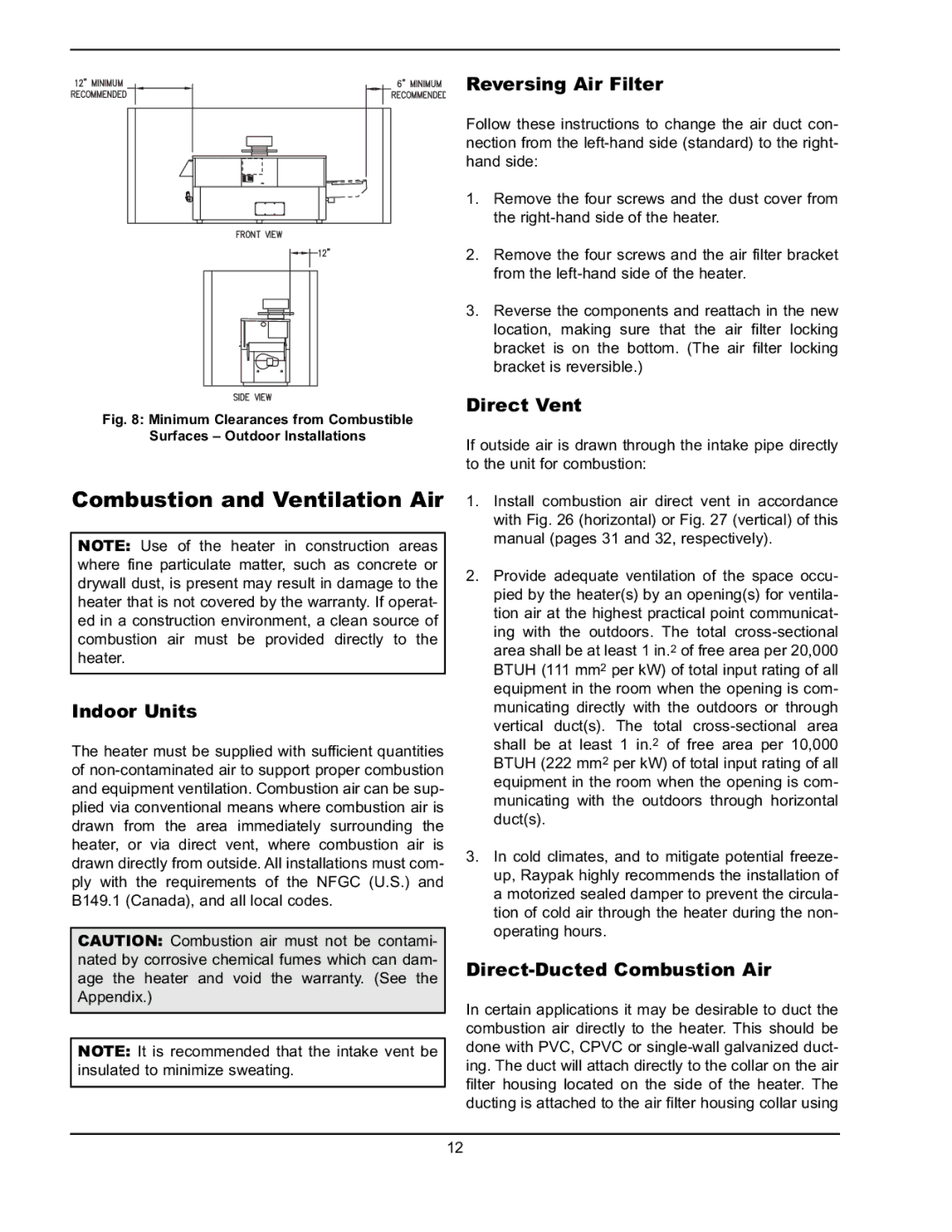
Fig. 8: Minimum Clearances from Combustible

Surfaces – Outdoor Installations

Combustion and Ventilation Air

NOTE: Use of the heater in construction areas where fine particulate matter, such as concrete or drywall dust, is present may result in damage to the heater that is not covered by the warranty. If operat- ed in a construction environment, a clean source of combustion air must be provided directly to the heater.

Indoor Units

The heater must be supplied with sufficient quantities of non-contaminated air to support proper combustion and equipment ventilation. Combustion air can be sup- plied via conventional means where combustion air is drawn from the area immediately surrounding the heater, or via direct vent, where combustion air is drawn directly from outside. All installations must com- ply with the requirements of the NFGC (U.S.) and B149.1 (Canada), and all local codes.

CAUTION: Combustion air must not be contami- nated by corrosive chemical fumes which can dam- age the heater and void the warranty. (See the Appendix.)

NOTE: It is recommended that the intake vent be insulated to minimize sweating.

Reversing Air Filter

Follow these instructions to change the air duct con- nection from the left-hand side (standard) to the right- hand side:

1.Remove the four screws and the dust cover from the right-hand side of the heater.

2.Remove the four screws and the air filter bracket from the left-hand side of the heater.

3.Reverse the components and reattach in the new location, making sure that the air filter locking bracket is on the bottom. (The air filter locking bracket is reversible.)

Direct Vent

If outside air is drawn through the intake pipe directly to the unit for combustion:

1.Install combustion air direct vent in accordance with Fig. 26 (horizontal) or Fig. 27 (vertical) of this manual (pages 31 and 32, respectively).

2.Provide adequate ventilation of the space occu- pied by the heater(s) by an opening(s) for ventila- tion air at the highest practical point communicat- ing with the outdoors. The total cross-sectional area shall be at least 1 in.2 of free area per 20,000 BTUH (111 mm2 per kW) of total input rating of all equipment in the room when the opening is com- municating directly with the outdoors or through vertical duct(s). The total cross-sectional area shall be at least 1 in.2 of free area per 10,000 BTUH (222 mm2 per kW) of total input rating of all equipment in the room when the opening is com- municating with the outdoors through horizontal duct(s).

3.In cold climates, and to mitigate potential freeze- up, Raypak highly recommends the installation of a motorized sealed damper to prevent the circula- tion of cold air through the heater during the non- operating hours.

Direct-Ducted Combustion Air

In certain applications it may be desirable to duct the combustion air directly to the heater. This should be done with PVC, CPVC or single-wall galvanized duct- ing. The duct will attach directly to the collar on the air filter housing located on the side of the heater. The ducting is attached to the air filter housing collar using

12

Page 12
Image 12
Raypak 302A-902A manual Combustion and Ventilation Air, Indoor Units, Reversing Air Filter, Direct Vent

302A-902A specifications

The Raypak 302A-902A is a highly regarded pool and spa heater, known for its efficiency and reliability in delivering warmth to residential and commercial aquatic applications. This heater stands out due to its robust design, advanced technology, and user-friendly features.

One of the key characteristics of the Raypak 302A-902A is its dual fuel capability, which means it can run on either natural gas or propane. This flexibility allows users to choose their preferred fuel type, contributing to operational efficiency and cost-effectiveness. With a BTU output ranging from 302,000 to 902,000, the Raypak heater is capable of quickly heating large volumes of water, making it ideal for pools, spas, and hot tubs.

The heater incorporates advanced technology such as a stainless steel heat exchanger, which not only ensures excellent thermal conductivity but also promotes durability against corrosion. This is especially advantageous in harsh environments, where exposure to chemicals can significantly impact the lifespan of traditional copper heat exchangers. The Raypak 302A-902A's heat exchanger is designed to withstand the rigors of constant use while maintaining high performance levels.

Another prominent feature of the Raypak 302A-902A is its digital display control system, which simplifies the operation and monitoring of the heater. Users can easily set and adjust temperatures, as well as access diagnostic information, all through an intuitive interface. This digital control not only enhances user experience but also aids in the timely maintenance of the unit.

Energy efficiency is another major selling point of the Raypak 302A-902A. The heater is designed with environmentally friendly practices in mind, utilizing a low NOx burner that minimizes harmful emissions. This not only meets environmental regulations but also makes it a greener alternative for heating needs.

In terms of installation, the compact design of the Raypak 302A-902A allows for versatile placement options, whether in a residential backyard or a commercial environment. Its user-friendly installation process ensures that homeowners and businesses alike can enjoy the benefits of heated water with minimal hassle.

Overall, the Raypak 302A-902A is an exemplary choice for anyone seeking a high-quality, efficient, and flexible pool and spa heating solution. Its combination of robust engineering, advanced technology, and user-focused features solidifies its position as a leader in the market, promising effective heating for years to come. Whether for personal enjoyment or commercial use, this heater delivers exceptional performance that meets diverse heating needs.