Manuals
/
Raypak
/
Lawn and Garden
/
Swimming Pool Heater
Raypak
manual
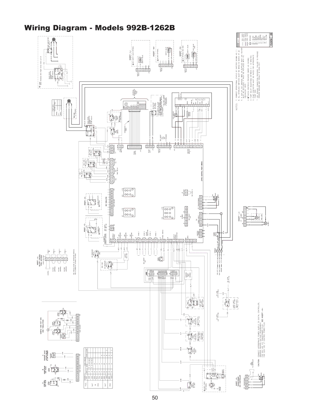
Wiring Diagram Models 992B-1262B
Models:
992B-1262B
1
50
66
66
Download
66 pages
19.05 Kb
47
48
49
50
51
52
53
54
Troubleshooting
Install
UDB Fault History
Field Wiring Connection
Maintenance
Venting Configurations
High Limit Manual Reset
Blower Adjustment
Temperature & Pressure Gauge
Safety
Page 50
Image 50
Wiring Diagram - Models
992B-1262B
50
Page 49
Page 51
Page 50
Image 50
Page 49
Page 51
Contents
Installation & Operating Instructions
Page
Contents
Pay Attention to These Terms
Product Receipt
Before Installation
Installations at Elevation
Model Identification
Component Locations
Component Locations Back
Valves
General Information
Model Quantity Vent Size Gas Burners Blowers
Model Burners per Valve Stages Fire at Stage
Water Time to Produce Serious Temp Burn
General Safety
Time/Temperature Relationships in Scalds
Equipment Base
Installation
Installation Codes
Stacking
Table D Vent/Air Inlet Termination Clearances
Clearances
Indoor Installations
Outdoor Installations
Reversing Air Filter
Combustion and Ventilation Air
Indoor Units
Direct Vent
TruSeal Combustion Air
Installations
Conventional Combustion Air Supply
All Air from Inside the Building
General
Canadian Installations
Water Piping
Reversing Water Connections
Relief Valve Piping Hydrostatic Test
Cold Water Operation
Pump Selection
Temperature & Pressure Gauge
Hydronic Heating
Air-Separation/Expansion Tank
Pressure Drop in Feet of Head Feedwater Regulator
Piping
Three-Way Valves
Potable Water and Space Heating
Pool Heating
Automatic Chlorinators and Chemical Feeders
Winterizing Your Heater
PH of Water
Gas Supply
Pool/Spa Water Chemistry Water Hardness
Total Dissolved Solids
Model
Gas Supply Connection
Reversing Gas Supply Connection
Table I Maximum Equivalent Pipe Length
Gas Supply Pressure
Electrical Power Connections
Check the Power Source
Field-Connected Controllers
Field Wiring Connection
Making the Electrical Connections
On-Off Wiring Connections
Model Diameter Order Number
Venting
Flue Exhaust Tee
Appliance Categories
Combustion Exhaust
Support of Vent Stack
Vent Terminal Location
Certified Combustion Air
Changing the Flue Outlet
Installations
Canadian Installations
Installation
Venting Installation Tips
Venting Configurations
Natural Draft Vertical Venting Category
Certified Vertical Venting Combustion Air Air Inlet Model
Termination
Common Venting System
Height
Horizontal Through-the-Wall Venting Category
Horizontal Through-the-Wall Venting Category
Venting
Direct Vent Horizontal Through- the-Wall
Model Certified Maximum Combustion Air Inlet
Equivalent Material Vent Length Intake Pipe
Direct Vent Vertical
Direct Vent Vertical
Freeze Protection
Outdoor Installation
Controls
Heater Sequence of Operation
Models 992B-1262B
External Lights Color Indication
Models 1532B 1802B
Page
Page
Models 2002B 2342B
Page
Page
Ignition Module
High Limit Manual Reset
Flow Switch
Operating Control
High and Low Gas Pressure Switches
Low Water Cut-Off Optional
UDB Diagnostic Board
UDB Fault History
Venting Appliance Categories
87%-Efficiency Boilers Special Instructions
Water Piping
Condensate Management
Vertical Venting Category
Vent Terminal Location
Max. Length Material Vent Length
Certified Maximum Combustion Air Air Inlet Model Venting
Equivalent
Direct Vent Horizontal Through- the-Wall
992BE 75’ 100’ 1262BE Galvanized Steel 1532BE Category 25’
Wiring Diagram Models 992B-1262B
Wiring Diagram Models 1532B-2342B
START-UP
Pre Start-up
Start-Up
Blower Adjustment
Main Burner Adjustment
Follow-Up
Safety Inspection
Leak Test Procedure Dual-Seat Gas Valves
Pilot Turn-Down Test
Post Start-Up Check
Leak Test
To Turn Off Gas To Appliance
Operation
Lighting Instructions
Troubleshooting
Step
Preventive Maintenance Schedule
Maintenance
Suggested Minimum Maintenance Schedule
Annually
Weekly
Semi-Annually
As Required
Appendix
Inside Air Contamination
Limited Parts Warranty HI Delta Types H and WH
Limited Parts Warranty HI Delta Type P
START-UP Checklist for FAN-ASSISTED Raypak Products
Page
Top
Page
Image
Contents