| Model | Certified |
| Maximum | Combustion | Air Inlet |
| |
|
| Air | Max. Length* |
| ||||
| Venting | Vent Size | Equivalent |
| ||||
| No. | Material |
| Vent Length* | Intake Pipe | 10” | 12” |
|
|
|
| Material |
| ||||
|
|
|
|
|
| |||
|
|
|
|
|
|
|
| |
|
|
|
|
|
|
|
|
|
| 992B |
| 10” |
|
|
|
|
|
|
|
|
| 70’ |
| 75’ | 100’ |
|
| 1262B |
| 12” | Galvanized |
| |||
|
|
| Room Air |
|
|
| ||
| 1532B |
|
|
|
| |||
|
|
|
| Steel, |
|
|
| |
|
|
|
| 40’ |
|
|
| |
| 1802B | Category III |
| PVC, |
|
|
| |
|
|
| 14” | Ducted | ABS, |
|
|
|
| 2002B |
|
|
|
| |||
|
| Combustion | CPVC | 40’ | 75’ |
| ||
|
|
|
|
| ||||
| 2072B |
|
| |||||
|
|
| Air |
|
|
|
| |
|
|
|
|
|
|
|
|
|
| 2342B |
| 16” |
|
|
|
|
|
|
|
|
|
|
|
|
|
|
* Subtract 10 ft per elbow. Max. 3 elbows.
Maximum combustion air duct length terminated at 100 equivalent ft.
Table L: Category III Horizontal and Direct Venting
Use only the special gas vent pipes listed for use with Category III gas burning heaters, such as the
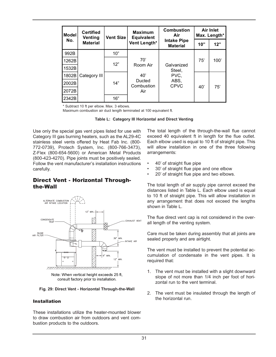
Direct Vent - Horizontal Through- the-Wall
Note: When vertical height exceeds 25 ft,
consult factory prior to installation.
Fig. 29: Direct Vent - Horizontal Through-the-Wall
Installation
These installations utilize the
The total length of the
•40’ of straight flue pipe
•30’ of straight flue pipe and one elbow
•20’ of straight flue pipe and two elbows.
The total length of air supply pipe cannot exceed the distances listed in Table L. Each elbow used is equal to 10 ft of straight pipe. This will allow installation in any arrangement that does not exceed the lengths shown in Table L.
The flue direct vent cap is not considered in the over- all length of the venting system.
Care must be taken during assembly that all joints are sealed properly and are airtight.
The vent must be installed to prevent the potential ac- cumulation of condensate in the vent pipes. It is required that:
1.The vent must be installed with a slight downward slope of not more than 1/4 inch per foot of hori- zontal run to the vent terminal.
2.The vent must be insulated through the length of the horizontal run.
31