Reversing Water Connections
Follow these instructions to change the water connec- tions from the left- hand side (standard) to the
1.Disconnect all electrical power from the heater (if applicable).
2.Label all electrical connections and conduit lines. This may include the flow switch, low water
3.Disconnect or isolate the main gas pipe from the heater (if applicable).
4.Remove both in/out and return header access panels by removing all sheet metal screws.
5.Remove all plumbing fittings to the header. This will include both inlet and outlet water pipe unions and the pressure relief valve and drain piping.
6.Remove limits, control bulbs and/or sensors.
7.Remove the six flange nuts and the in/out header from the
8.Remove the six flange nuts and the return header from the
9.Remove the header stud bolts from each tube sheet.
10.Reverse the headers and stud bolts to the new location.
11.Install NEW red beveled
12.Push the header firmly against the
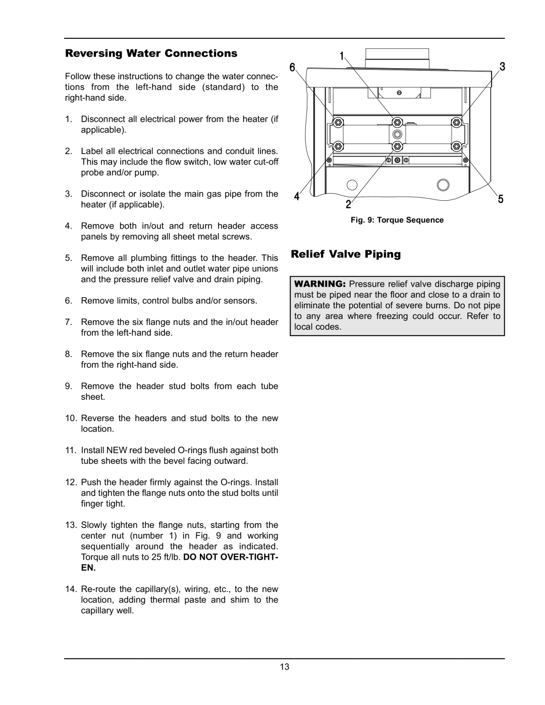
13.Slowly tighten the flange nuts, starting from the center nut (number 1) in Fig. 9 and working sequentially around the header as indicated. Torque all nuts to 25 ft/lb. DO NOT
EN.
14.
Fig. 9: Torque Sequence
Relief Valve Piping
WARNING: Pressure relief valve discharge piping must be piped near the floor and close to a drain to eliminate the potential of severe burns. Do not pipe to any area where freezing could occur. Refer to local codes.
13