Model | Input | 3/4” |
| 1” | ||||||
|
|
|
|
|
|
|
|
|
| |
No. | (KBTUH) | N | P | N |
| P | N | P | N | P |
HD101 | 100 | 105 | 385 | 340 |
|
|
|
|
|
|
HD151 | 150 | 50 | 180 | 160 |
| 530 | 600 |
|
|
|
|
|
|
| |||||||
HD201 | 199 | 30 | 95 | 95 | 355 | 360 |
|
|
| |
|
|
| ||||||||
HD251 | 250 | 20 | 50 | 60 | 230 | 240 |
|
|
| |
HD301 | 299 | 15 | 35 | 45 | 170 | 170 | 550 | 360 |
| |
HD401 | 399 | 5 | 20 | 25 | 80 | 100 | 365 | 210 |
| |
Table H: Maximum Equivalent Pipe Length
Natural gas – 1,000 BTUH per ft3, .60 specific gravity at 0.5 in. WC pressure drop Propane gas – 2,500 BTUH per ft3, 1.50 specific gravity at 0.5 in. WC pressure drop
Install a separate disconnect means for each load. Use
It is strongly recommended that all
Surge Protection
If any of the original wire as supplied with the heater must be replaced, it must be replaced with 105°C wire or its equivalent.
Check the Power Source
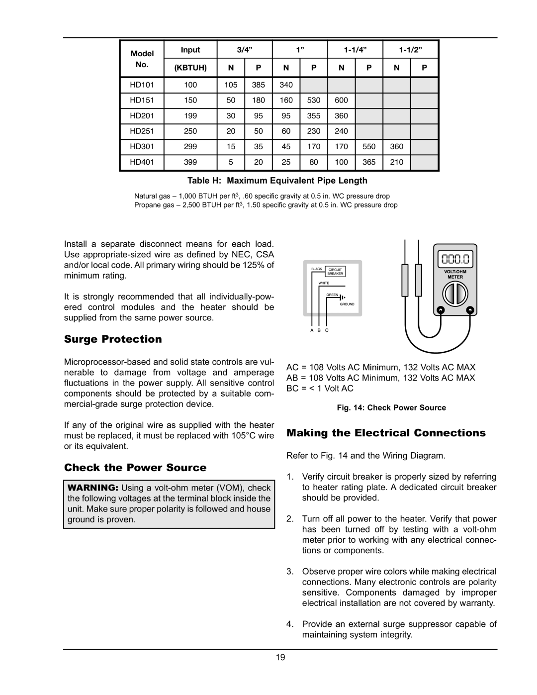
WARNING: Using a
AC = 108 Volts AC Minimum, 132 Volts AC MAX AB = 108 Volts AC Minimum, 132 Volts AC MAX BC = < 1 Volt AC
Fig. 14: Check Power Source
Making the Electrical Connections
Refer to Fig. 14 and the Wiring Diagram.
1.Verify circuit breaker is properly sized by referring to heater rating plate. A dedicated circuit breaker should be provided.
2.Turn off all power to the heater. Verify that power has been turned off by testing with a
3.Observe proper wire colors while making electrical connections. Many electronic controls are polarity sensitive. Components damaged by improper electrical installation are not covered by warranty.
4.Provide an external surge suppressor capable of maintaining system integrity.
19